


Custom DIY Solder Reflow Oven Project
Initial testing of my 16" wide custom DIY solder reflow oven
Introduction
Despite having a full complement of professional soldering tools at my disposal, after manually soldering my share of prototype boards I recently came to the conclusion that I needed a reflow soldering oven so I could place all the parts on my boards, reflow them, and get on with more important things, like developing the software to run on them.
The problem is most of the commercial units are many thousands of dollars, extremely heavy (often over 100 pounds) and wired for 220V, something I lacked in a convenient location. I began looking at some of the cheaper Chinese units designed for bench mounting but discussions I found online mostly panned the lower end models, and, interestingly enough, some of the models in the $3K range too.
So I naturally decided to build an oven myself. I figured in the worst case scenario I'd finish the project, it wouldn't work, and I'd be forced to buy a commercial oven, but I'd come away with the experience needed to justify spending that extra money. After several months of on-and-off design and sourcing of parts I finally managed to complete the assembly of the unit. This article will describe some of my design methodology and the operational results of the finished unit.
Chassis
Although I have a copy of Solidworks and could have constructed the chassis myself time was the limiting factor here so I bought an Oster convection oven, model number TSSTTVDGXL-SHP, stripped it of its controller and other parts, and used the basic frame as the foundation for my project.
This particular oven was selected because of its 16" interior width. While most of my boards are pretty small I was working on a project with a board roughly 13.5" x 2.5", which would obviously not fit in the smaller toaster ovens typically used for projects like this. I also wanted the option to fit an entire panel of these boards, and I found most toaster ovens had interior dimensions of 11"x 8" at best.
The one significant downside to the oven I selected was that it came equipped with metallic heating elements, which are unsuitable for reflow operations due to their thermal inertia, i.e. they take too long to heat up and cool down. This property would prevent the controller from tightly controlling the temperature of the oven and sticking to the prescribed reflow temperature profile. This meant ripping out the metallic elements and finding a source for quartz infrared heating elements to replace them.
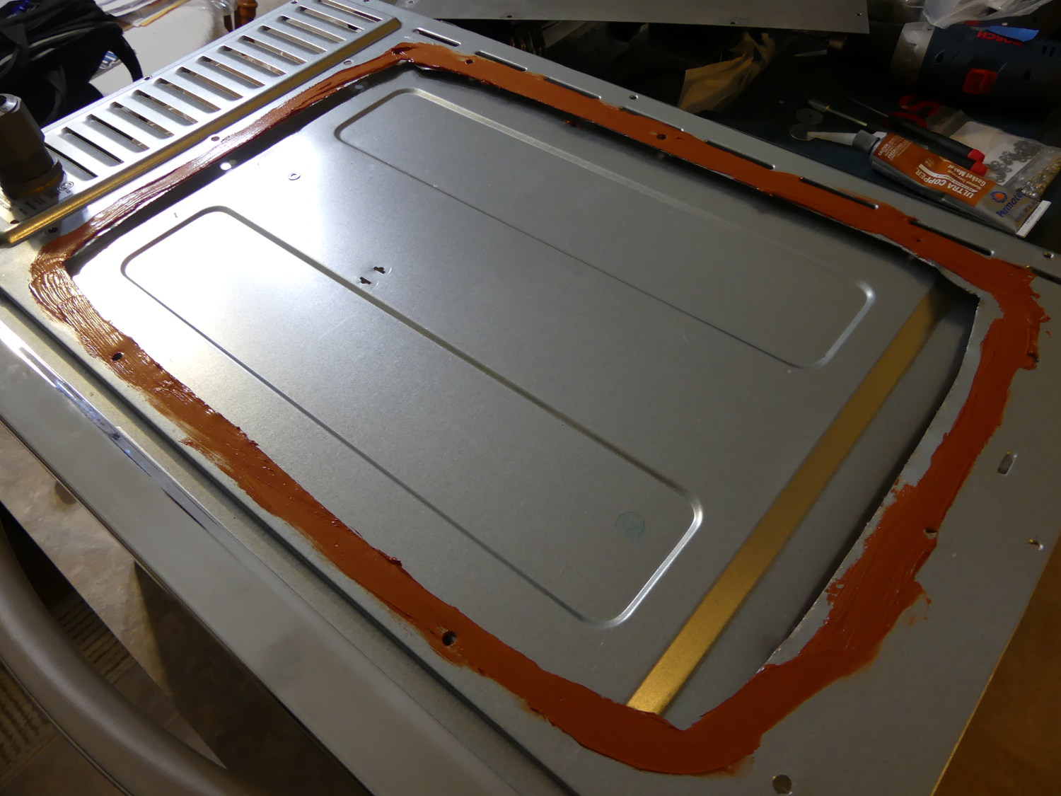 The rear of the oven was rounded and extended beyond the face by a good 4 inches. I replaced it with a panel fabricated from 20 gauge plate steel and sealed it high temp silicone. |
 A closeup of the power inlet wiring. I used 12/2 SJ cord and a plastic SJ cord adapter. I like using this kind of connector vs a traditional press-fit strain relief because it's easier to remove the cable if necessary. |
 The thin metal necessitated the creation of four additional plates used to support the heating elements. The ones intended to be installed permanently were sealed with high temp silicone. |
Another downside to this oven, and indeed all commercial ovens of this sort, is the fact that the metal is extremely thin. Drilling it often resulted in the metal tearing or billowing out on the far side. I had to use a countersinking bit on all holes, and the largest holes in particular, to remove the metal that would have otherwise prevented the hardware and fixtures from seating properly. I also donated at least a pint of blood while working with this chassis and at one point had a bandaid on 9 of 10 fingers. I shit you not. The crazy thing is perhaps 90% of the time I didn't know I cut myself until I noticed drops of blood on something. Yea, the metal was that sharp. Do yourself a favor and work with gloves if you can. That reminds me. I think I need a Tetanus booster.
One other glitch I ran into involved dealing with the door return hinge and spring assembly which by default interfered with the location I'd chosen for the front lower heating element. To remedy the problem I installed a post that pushed the spring up sufficiently to get the hinge far enough away from the element. This took a few trials and some head scratching, but it worked. If I were building a commercial oven I'd likely implement a tray design if for no other reason than to avoid this problem.
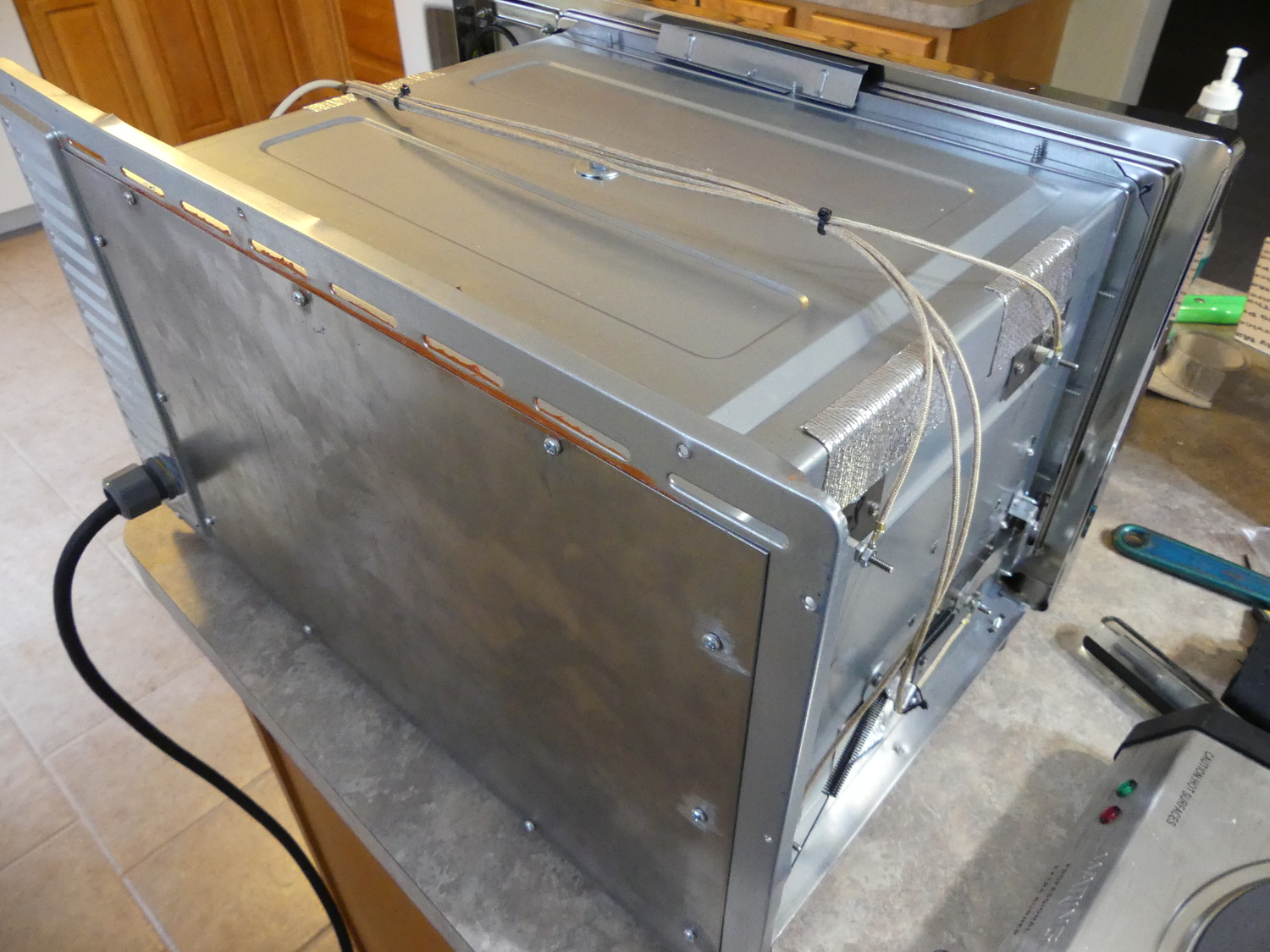 This shows the custom panel installed on the rear of the oven and the power inlet cord connector. Also evident is the 250C rated wire used to complete the heating element circuits. |
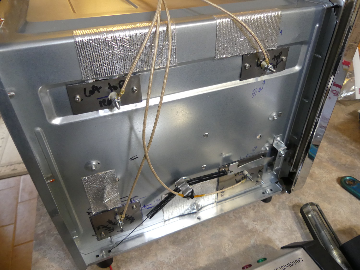 The left side shows the crimp style ring terminals make easy work of connecting the wire to the heating element binding posts. As you can tell there isn't much room betwen the inner and outer walls. The binding posts clear. |
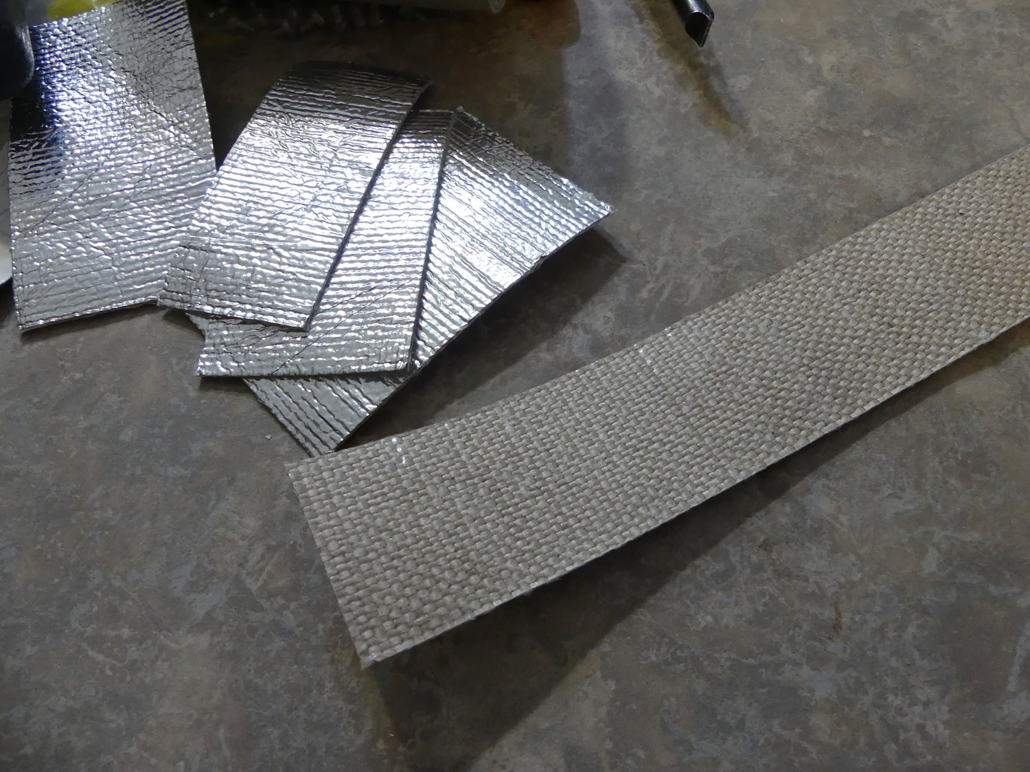 This is a closeup of the Heatshield Products insulation I used on the interior of the oven. The long piece is shown just prior to installation. With the protective film removed from the adhesive the fiberglass mat is clearly visible. |
Quartz Infrared Heating Elements
Design factors influencing my quartz infrared heating element selection included:
-
overall width (including terminations)
-
installed width (between insulator mounting surfaces)
-
power requirements
-
quartz glass finish (clear or frosted)
I had to be concerned with overall width including terminations because there simply wasn't much room between the oven interior box (the place where the heat is contained) and the exterior enclosure. I settled on binding post terminations instead of preinstalled high temperature wire because the latter were more expensive, not field replaceable, and longer overall. The binding post allows the wire to be mounted with a ring terminal which causes the wire to exit perpendicular to the post. This minmizes the overall dimension and reduces stress on the wire, as well as the chance that the wire will rub up against the exterior enclosure.
The overall interior of the oven enclosure turned out to be exactly 16 inches, but the material had been embossed in several locations apparently to improve the rigidity of the very thin metal, particularly in the locations where I planned to mount the top elements. I settled on units 15.75" in width (measured from the step on the insulator) and figured I'd shim them up as needed.
When it came to power, this was a fairly easy decision. I knew up front that I was limited to a 20A 120V circuit. As an electrician in a former life I was exposed to various rules of thumb and good design practices advocated (or required in many cases) by the US National Electrical Code. One of those design guidelines is related to the design load (not the maximum tolerable load) of a given circuit. Common residential and commercial circuits are usually designed for a running load of 80% of the maximum load allowed based on the wire gauge. 80% of 20A is of course 16A, and sure enough, that's about what four 500W heating elements draw in total.
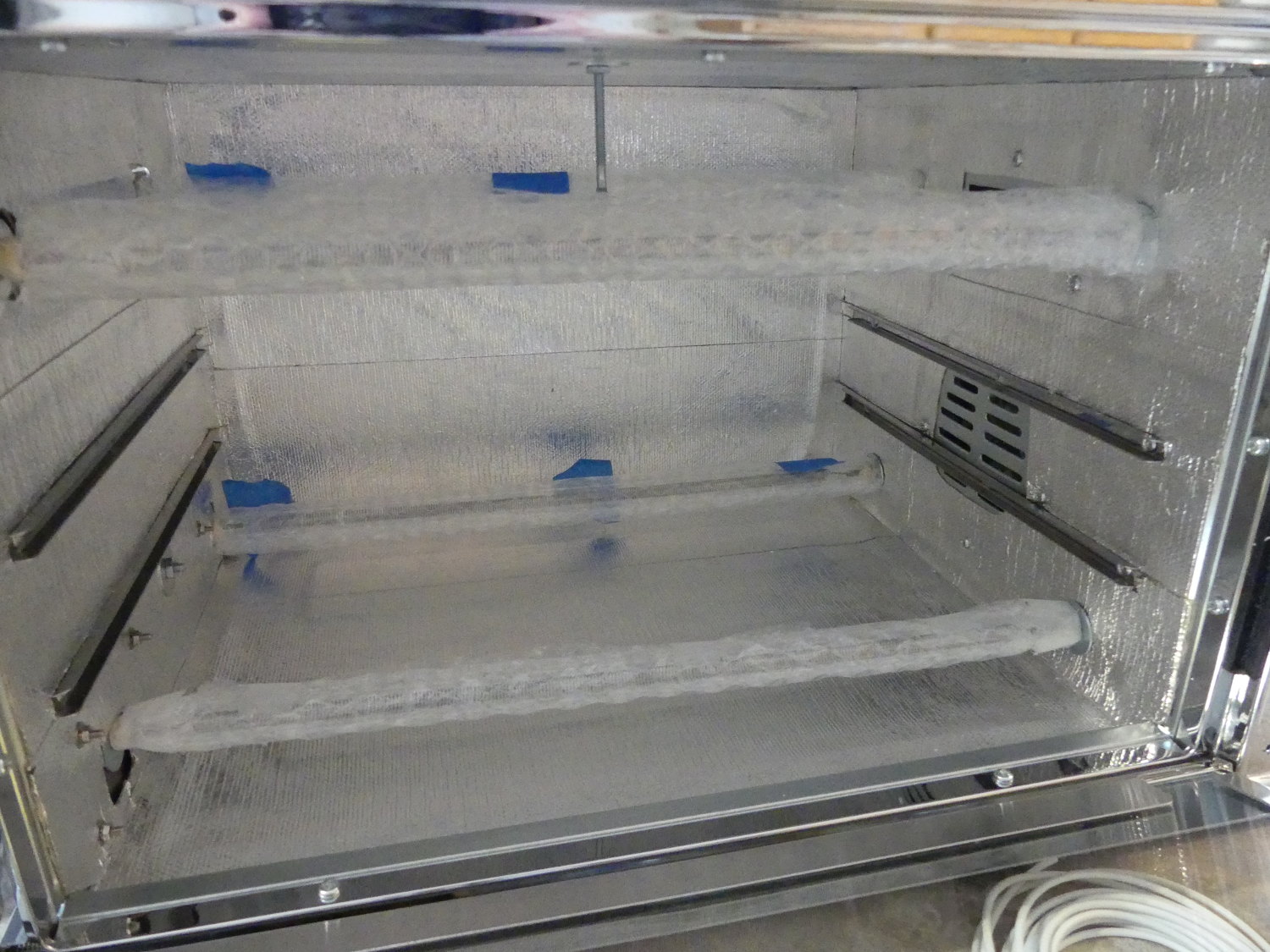
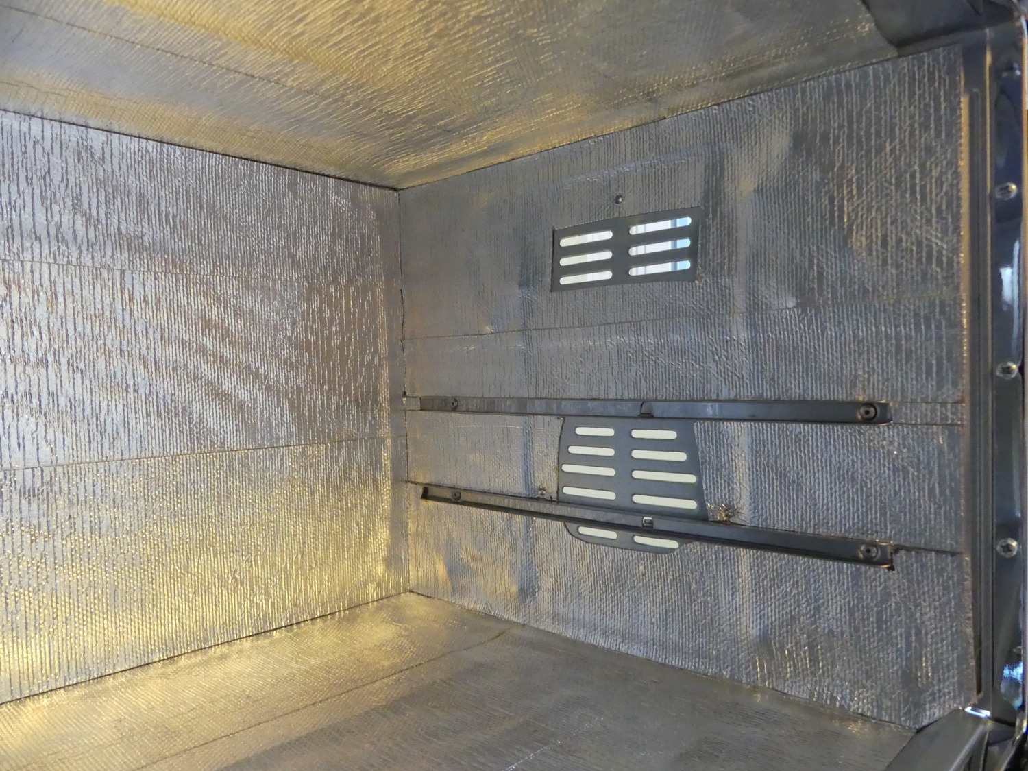 Lining the interior and glass door required 2 rolls of material. I did not remove the tray rails. I simply worked around them. Naturally, I cut out sections to accommodate the convection fan. |
 The heating elements came well packaged and were individually wrapped in bubble wrap. As it's important not to touch the glass during installation I left a bit of the material in place to protect the units. |
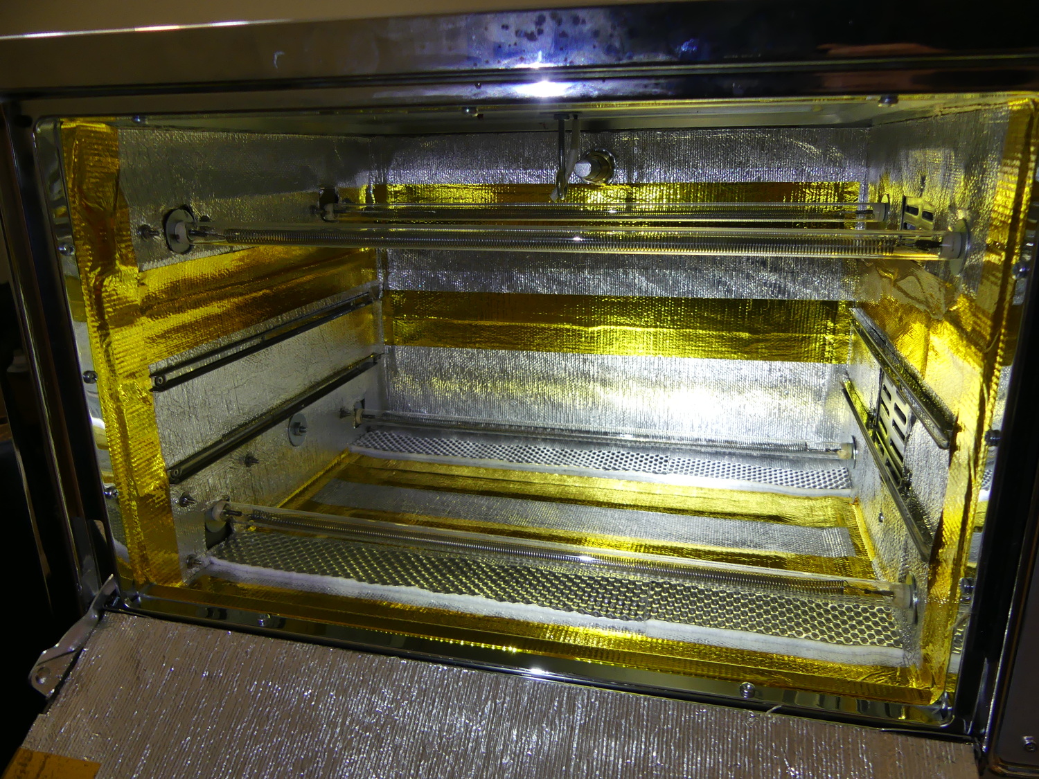
 Inserting my hand into the oven during this test I felt heat not just directly from the element but from all directions, as if immersing my hand in warm water. In other words, the reflective insulation was doing its job. |
When looking at various smaller commercial toaster ovens I found they came equipped with quartz elements that were frosted in appearance. I couldn't find a lot of information on the differences between the frosted elements, but one site indicated the frosted glass shifts the infrared wavelength a bit and reduces effective output by 30% as compared to clear glass. As I knew up front I was building a bigger oven, was limited in the total power I could throw at the system, and saw no point in altering the wavelength or reducing the efficiency of the elements I decided to select clear quartz glass.
I found three local quartz element manufacturers that seemed able to produce what I needed but none of the manufacturers I contacted via email responded so I called them one by one. In the end, the company that answered the phone got the order (let that be a lesson to the other companies!) Although I got the distinct sense that they were incredibly disorganized they promised a two week turn and I received the units in about three weeks.
Reflow Controller
The idea of using a microcontroller as a PID controller to modulate the output of some heating elements isn't exactly a new idea. I found the net replete with reflow oven controllers but few finished, polished designs shipping in quantity. I contemplated building my own briefly but quickly realized my schedule would not permit the indulgence.
After a bit of research I discovered and purchased the Controleo2 , manufactured by Whizoo.com and originally bootstrapped by Kickstarter. Despite a small glitch revealed by my custom design the controller functions as advertised, which is saying a lot in an age of bubbly tech, where marketing often trumps engineering.
The controller was available separately or as part of a larger kit. Although I purchased the full kit for $190 I did so before I had nailed down all of the requirements of my design so I wound up not using several of the components. If I had to do it over again I'd buy the controller only and source the few parts from the kit I needed from other vendors as that would have been the cheaper option.
Custom Front Panel
Although the Controleo2 is typically mounted in a plastic box on the exterior of the oven and rigged up with a servo to open the door I quickly decided against that because I didn't like the fragility of that design and saw no harm in opening the door myself a few inches. After all, I knew I would never walk away from the oven while in use so it was hardly an inconvenience.
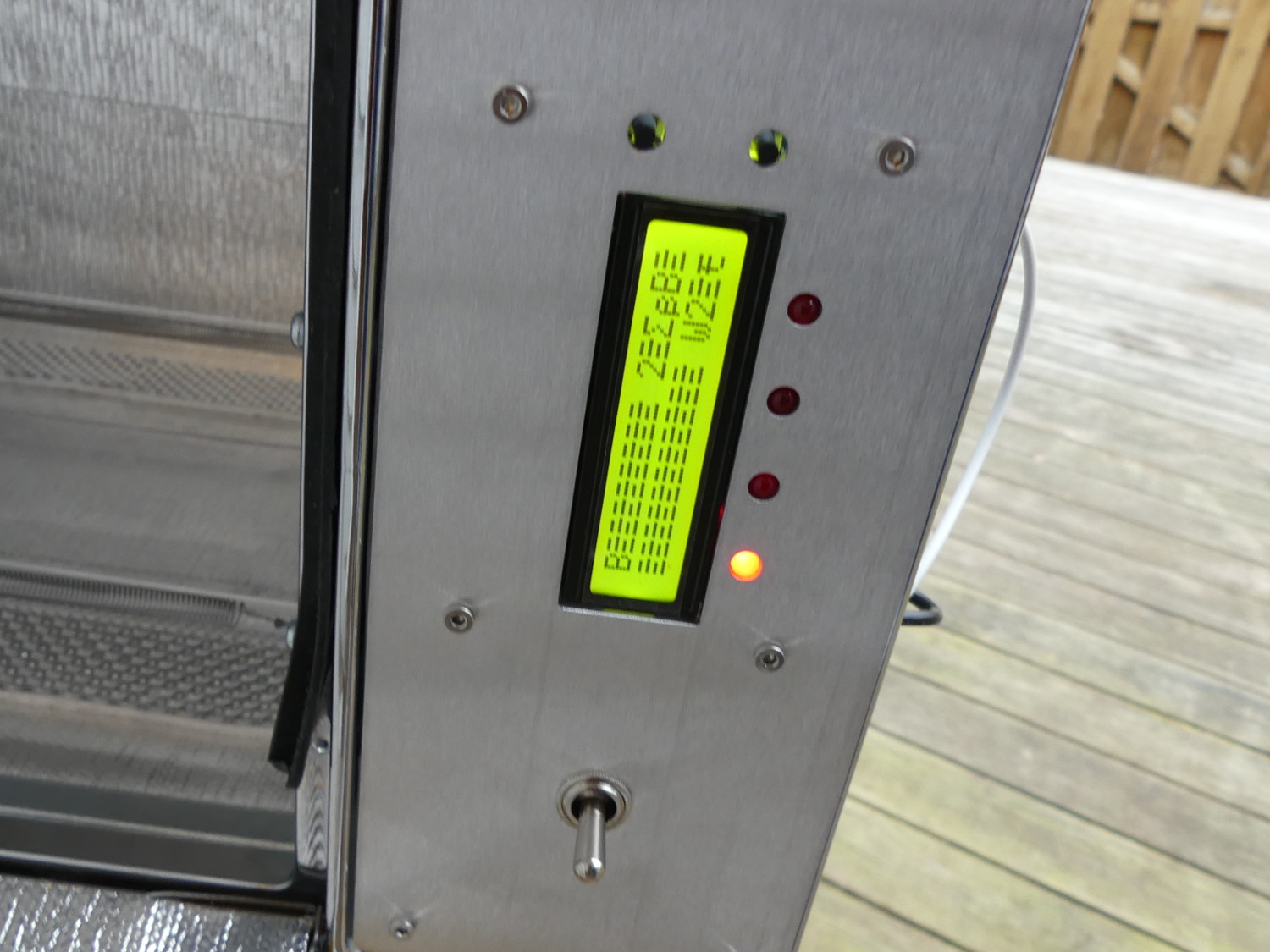 Here's a shot I took of the LCD display glitch that Peter and I ultimately traced to an ill-advised bonding of circuit ground and mains earth. The theory was that noise was getting into the LCD data lines whenever I'd approach or touch the metal panel. |
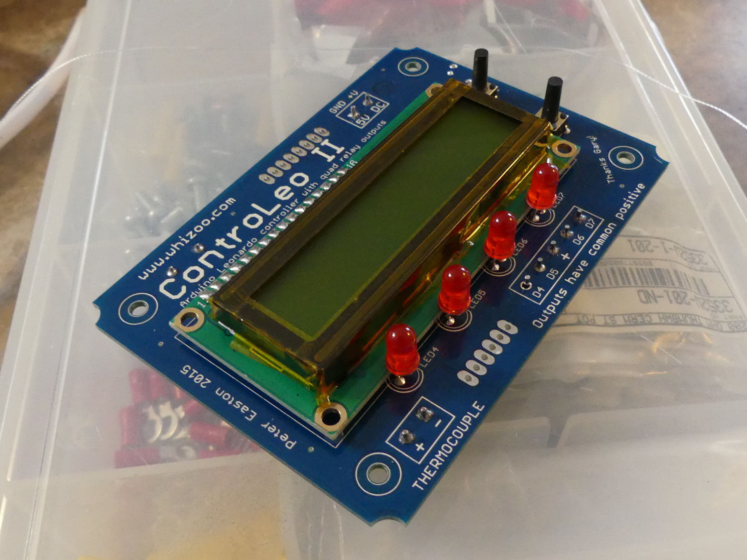 A closeup of the controller just before I reinstalled it with kapton tape wrapped completely around the frame. This served to insulate the LCD frame which is tied to circuit / signal ground. The tape prevents noise from mains earth from contaminating the circuit ground. |
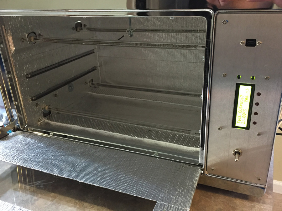
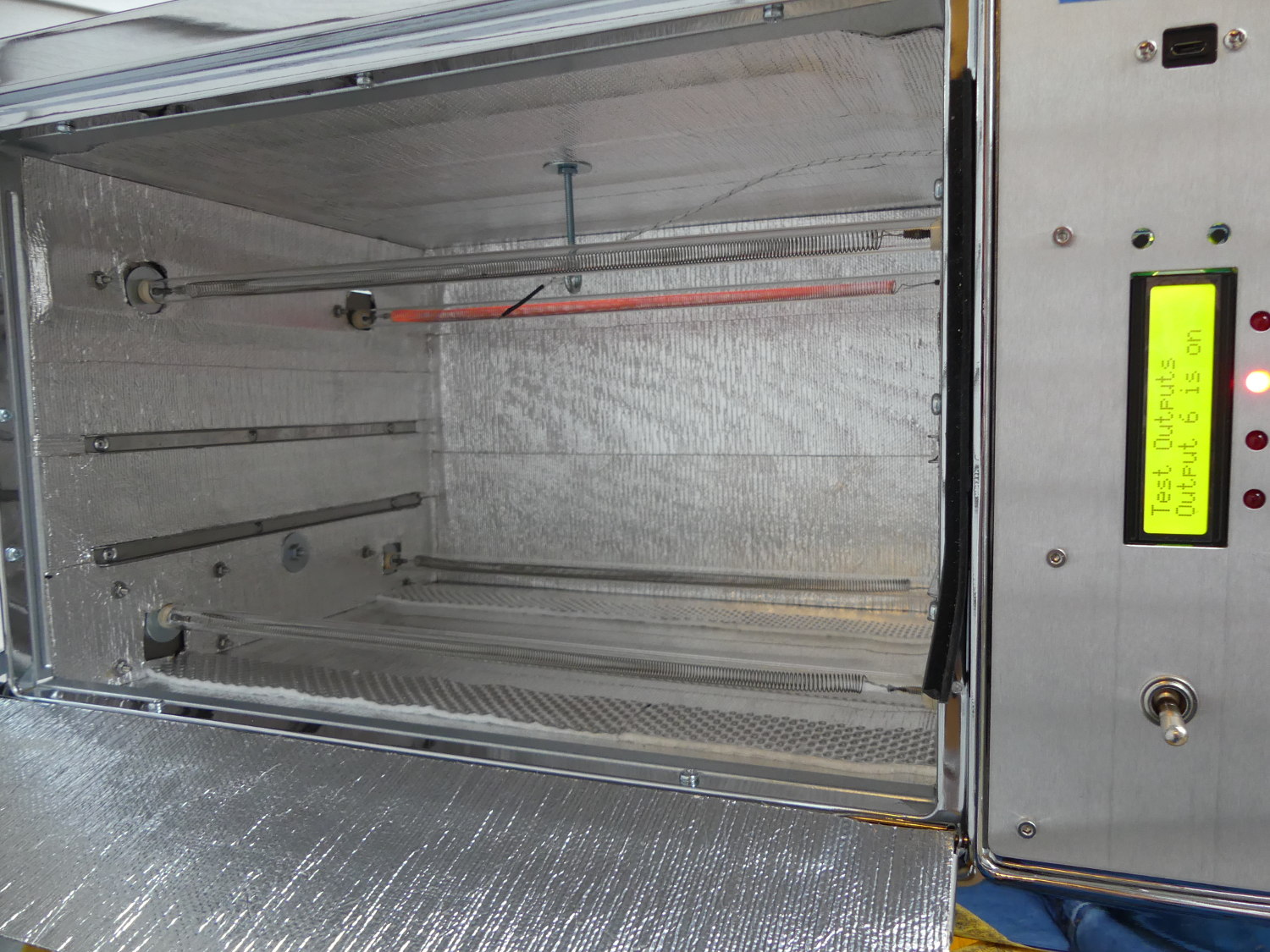
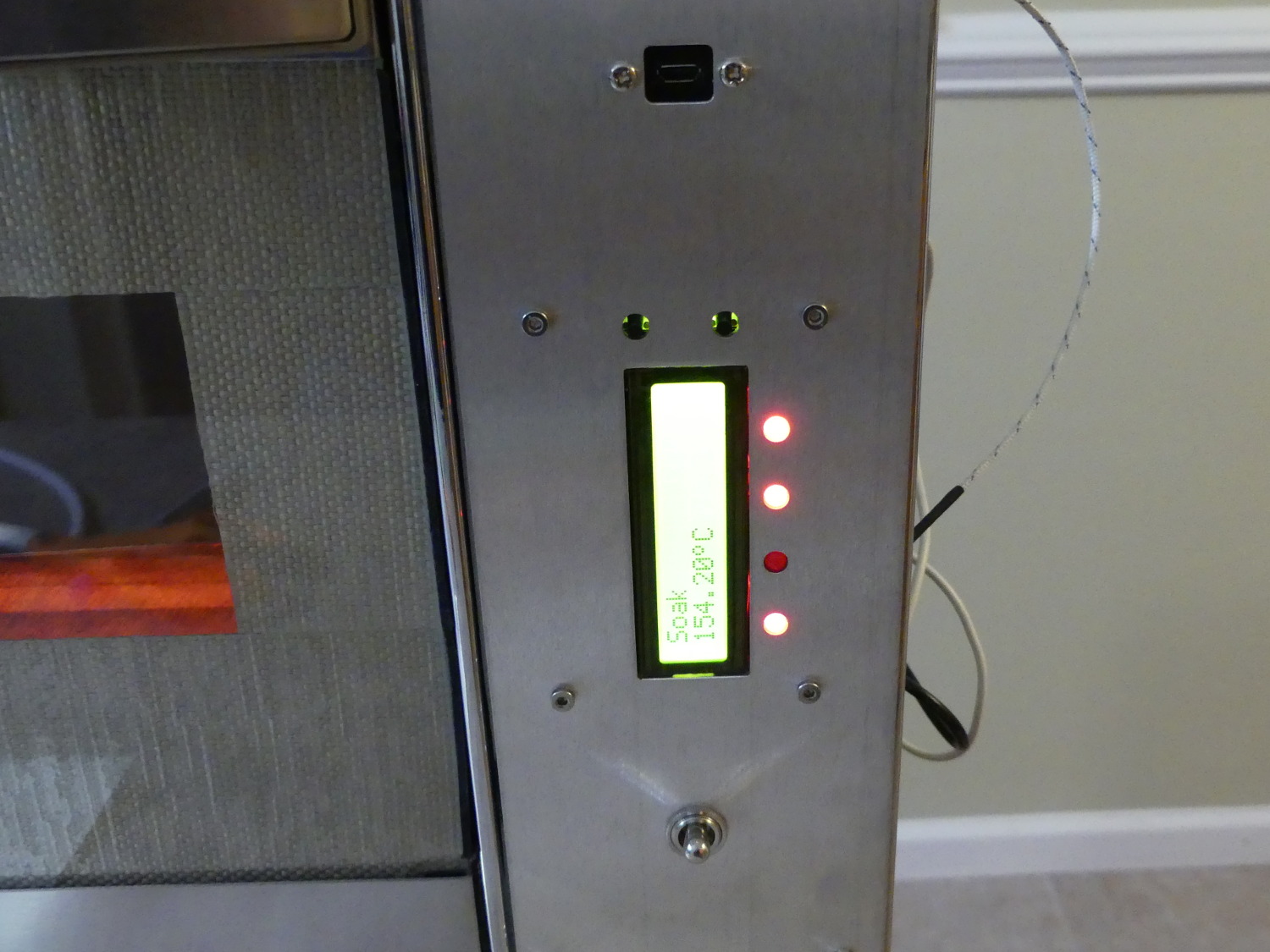 Here the new controller is in testing, proceeding through the soak phase of the reflow process. The thermocouple is reading a temperature of roughly 154C. Right on target. Note the bottom elements are on at a higher duty cycle during the soak phase as the point is to heat the entire board. |
Instead, I decided to mate the controller to a custom front panel that would replace the oven's factory control panel. I worked up the part in Solidworks, and with help from Peter at Whizoo, used the very same dimensions he used to produce the custom plastic enclosure. The end result was a perfect fit of the controller to the panel and a design that looks just this side of a production oven.
While I was at it, I added a USB Micro-B Female to Micro-B Male panel mount extension cable so I would not have to remove the exterior enclosure to gain access to program the microcontroller or monitor the console output during a reflow. I wrapped up the CAD work by providing a hole to accept the convection fan switch required because the Controleo2 lacked a solid state relay output that would have allowed automatic control of the fan. As it turned out, I tend to turn the fan on before the reflow process starts and leave it on to help cool the oven down with the door open, so I'm not missing anything, really. But more about that later.
If there is a downside to my particular implementation is that's the Controleo2 uses a fixed 2 line LCD display and I had to mount the board vertically so the display text isn't horizontal. That is largely a cosmetic issue, as far as I'm concerned. Though if I were building my own controller I'd equip it with a matrix LCD that would allow me to change the orientation of the text so the board could be mounted either way.
I also noticed a problem during initial testing that was the result of the Controleo2 design in combination with my use of a metal front panel. While actuating buttons or touching the front panel the display would glitch and show garbage characters. The only solution was a power cycle, but the problem would consistently reoccur. I wound up sending the unit back to Whizoo but Peter reported it worked okay in his lab. We ultimately figured out that the problem was likely caused by the metal frame of the LCD, which is tied to DC / circuit ground, contacting my custom metal front panel, which is bonded to mains earth. Mains earth can be noisy, which may have disrupted the data lines going to the LCD. I'm apparently the first to install the controller in a front panel so it's no surprise he had never seen this condition except during development. I solved the problem by wrapping the metal LCD frame in kapton tape and thus providing electrical insulation between DC ground and mains earth. Once reinstalled, the controller worked flawlessly.
I'll take this time to point out that Peter has always responded to email quickly, sometimes within a couple hours, and he supported me after the sale. If you feel the Controleo2 will meet your needs you needn't worry about support.
Solid State Relays and Thermal Design
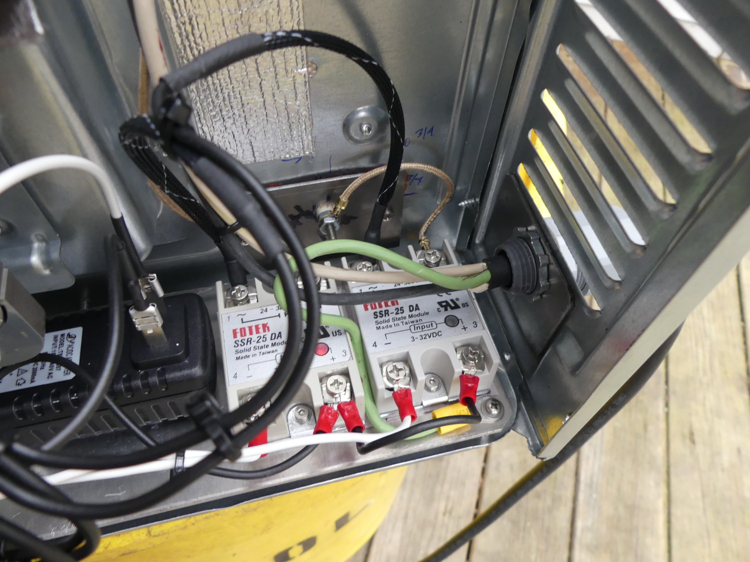
I used the three Fotek solid state relays provided in the Whizoo kit (part number SSR-25 DA), and bought two extras online, one for the fourth heating element and the other to serve as a spare since these aren't exactly high end units.
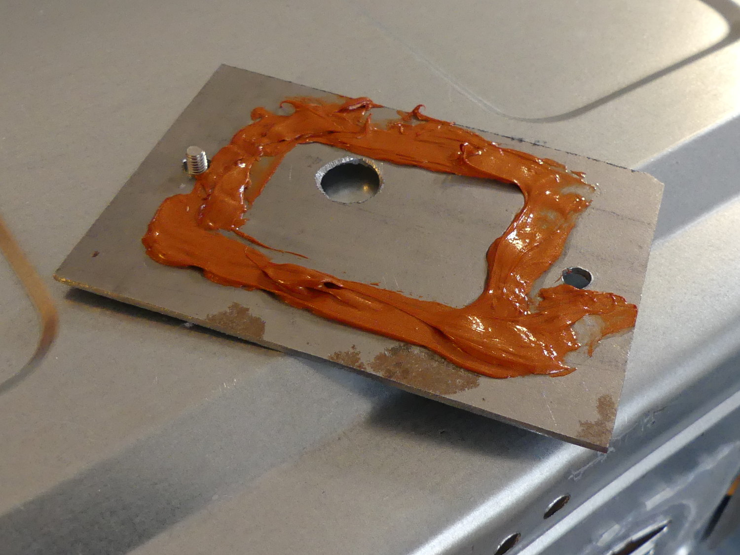
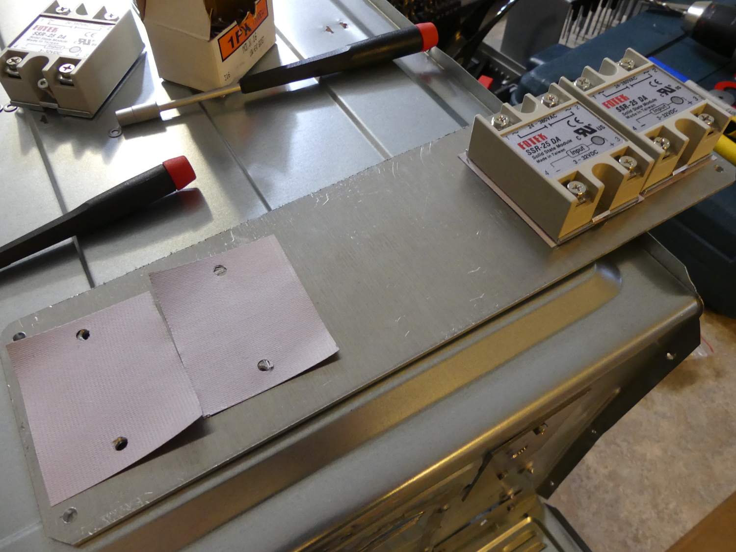 I used Keratherm to reduce the thermal resistance between the solid state relays and the mounting plate / heatsink. The holes were punched where needed with a leather hole punch. It's not perfect, but far better than any other method I found. |
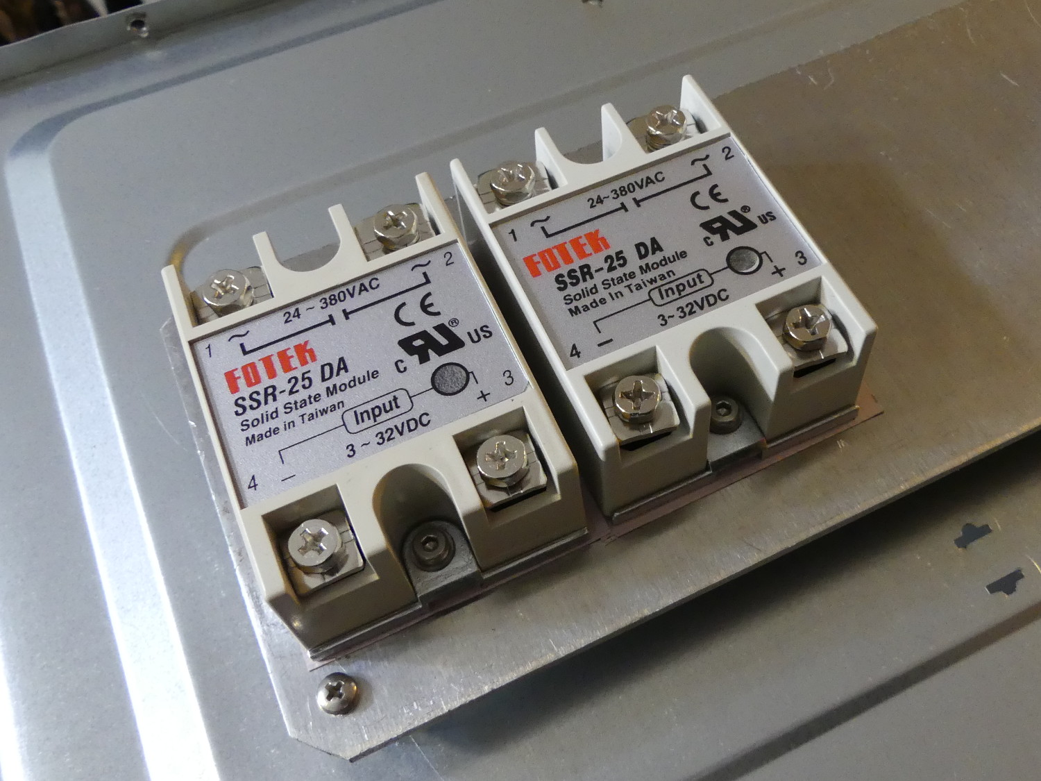 Showing the two SSRs mounted to the panel with the Keratherm barely visible. Here you can see the translucent window in the overlay on the relays. That's a red status LED that turns on when the relay is on. It's helpful for troubleshooting. |
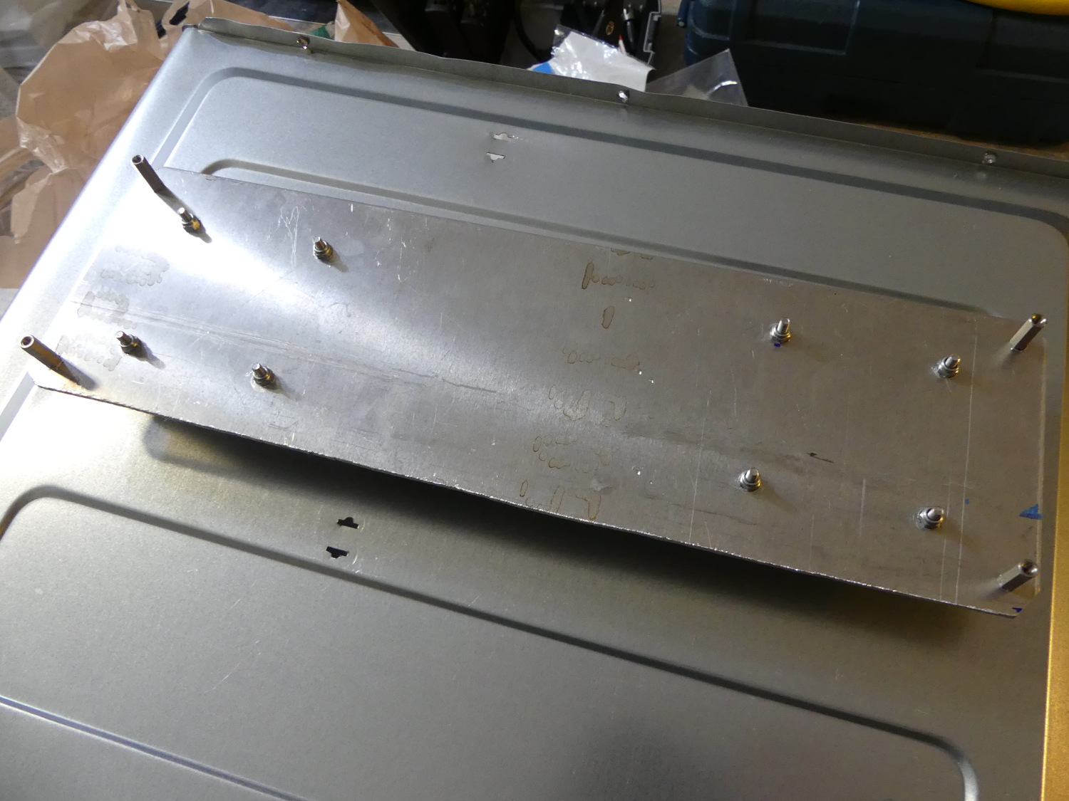 I used M3 hardware including nylon locknuts I had in stock to fasten the SSRs to the panel, and then used 16mm metal standoffs to electrically bond the panel with the chassis. |
As their model number implies the units are rated to 25A, but to support that kind of load they would need to be mated to an exceptionally large heatsink. Fortunately each heating element in my design requires only 4.5A so I was able to mount all four units on a piece of 3mm 6061 T6 aluminum plate I had in stock.
The SSRs do not need to be electrically insulated from their mounting plate / heatsink so I could have just mounted them directly to the heatsink. However, as heat is the enemy of all semiconductors, including SSRs, it's important to dissipate the heat normally generated during operation of the relay as efficiently as possible. This requires a heatsink of appropriate size and minimizing the thermal resistance between the relays and the heatsink. Mica and grease is often used in the audio world for this purpose but is quite messy. Whizoo provides a square of some unidentified material but I found this of insufficient size to do the job. My company sells Keratherm so I naturally used this material instead.
Incidentally, should you decide to purchase Keratherm through my company one "unit" of Keratherm is enough for two SSRs, so you'll need two units for this project.
Interior Insulation
I wound up not using the gold insulation provided in the Whizoo kit, mostly because one roll was inadequate for the size of my oven, but also because I found a product manufactured by Heatshield Products that was advertised as tolerating higher temperatures (1100F indirect, 500F direct, 1 inch airgap required). I had heard stories of insulation failing in ovens like this so I wanted all the design margin I could get.
During the first few learning runs of the oven I was happy with my choice as the material very effectively insulated the oven...to the point that I could rest my hand on the top of the oven for an extended time with no discomfort. But the first few learning runs did not complete and so the peak reflow temperature (240C / 464F) was never reached. A few runs later the oven finished a single reflow cycle. I found the top of the oven become noticeably hotter and, after opening the door, I found the adhesive of the material failed in spots. I pressed the material down and it appeared to stick but the adhesive didn't seem as resilient.
Regardless of the temperature rating on the box the adhesive is clearly inadequate for this design. This is particularly annoying considering that the peak temperature was never reached, I never exceeded even the lower temperature limit for the product, and in any case the peak temperature is only maintained for a few seconds before the cooldown begins.
I am not confident the mateiral will last more than a few reflow cycles, if that. So what would I do if I had to do it all over again? I'd probably put the insulation on the outside and accept the fact that the interior would not be as effective in reflecting the infrared radiation from the heating elements.
Wiring and Related Components
I bought a 25 foot roll of 12/2 SJ cord and a plastic SJ cord connector from my local electrical supply house and a Milwaukee Vari-Bit as required to drill the hole for the connector. Because the chassis metal was so thin I fabricated a doubler and drilled that as well. The end result is quite strong and at no risk of pulling out.
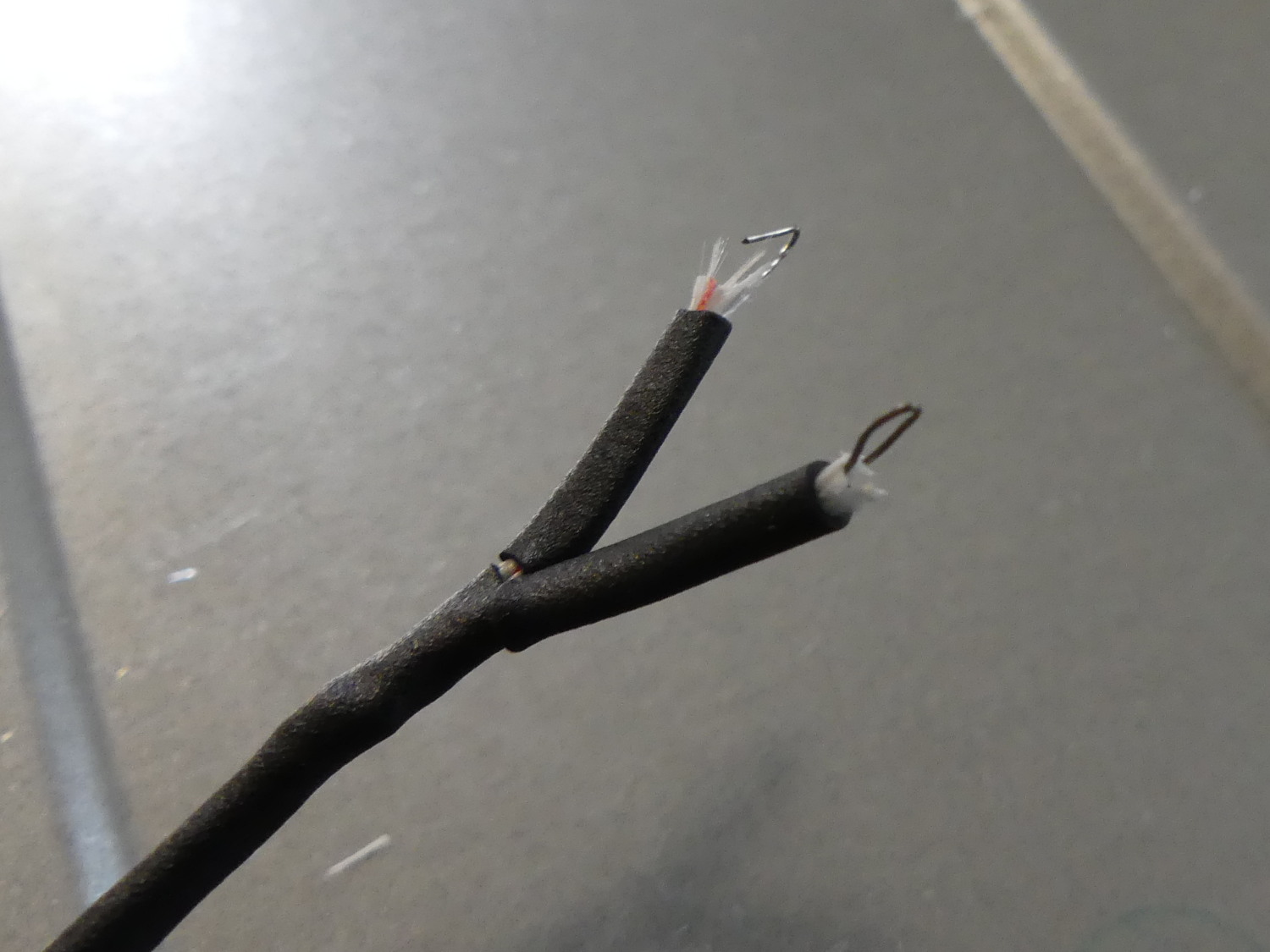 The thermocouple wires are extremely thin and must be doubled up before inserting them into the terminals on the controller board or it's quite likely tightening the screw will sever them. Protecting them inside the oven where they are exposed to high temperatures is also essential! |
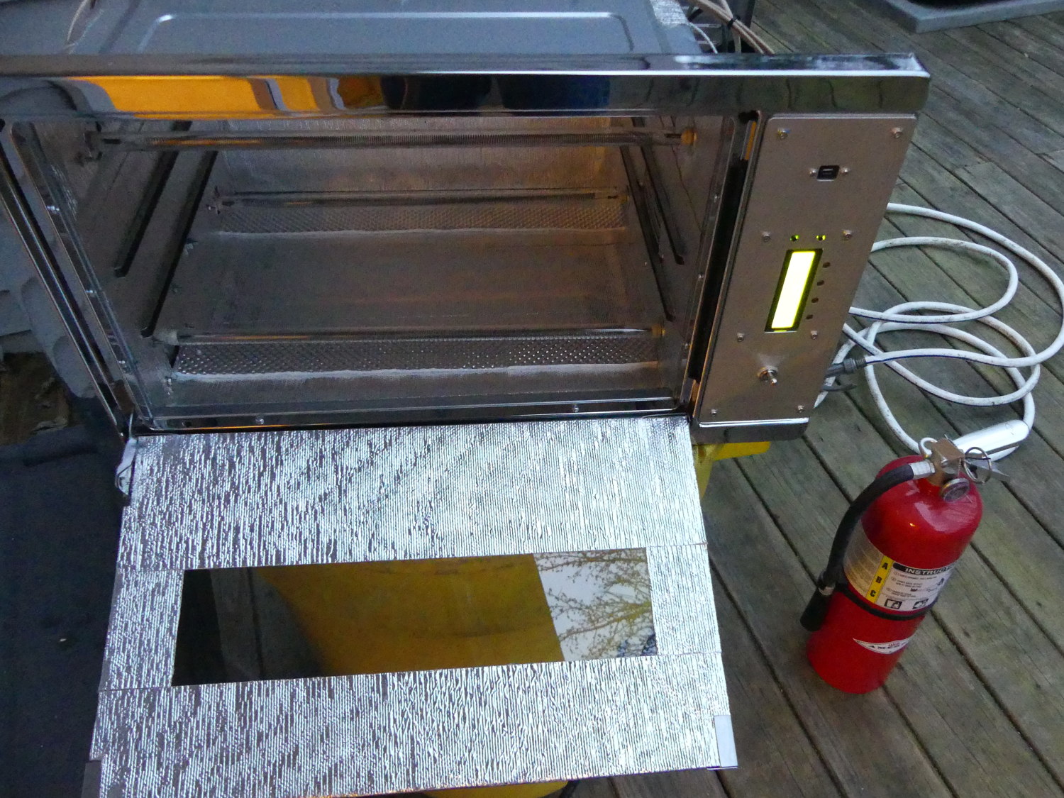 While many of the pictures in this article were taken indoors the first runs of the oven were outside with a fire extinguisher handy. It's not that I don't trust myself -- I didn't trust the insulation manufacturer. Water was also available but I wouln't use that unless the unit was unplugged first, naturally. |
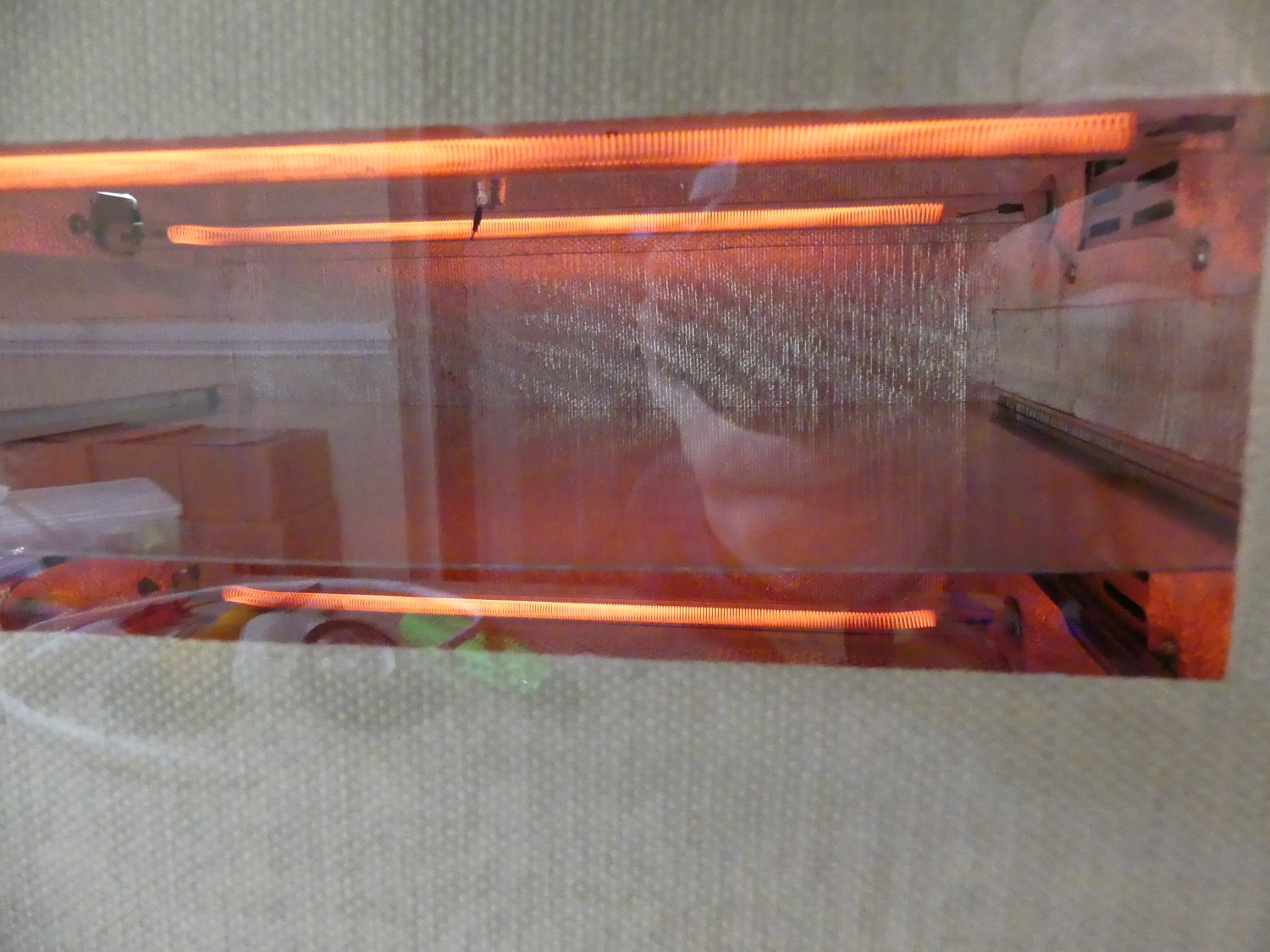 Ah, the satisfying glow of a reflow phase ramp of the heating elements. It's actually rare to see all elements like this. The duty cycle bias favors the bottom elements which are beneath the shelf. The top elements spend most of the time cycling on and off to the point they don't noticeably glow. |
The power inlet wiring terminated on a terminal block that I used to create the six individual circuits required to power the heating elements, convection fan, and controller power supply. I used 250C rated wire for all connections that terminated on the heating elements, as I knew the insulation of common 90C building wire would dry out and flake off. I also avoided using any heatshrink on those connections for the same reason.
All other wiring used 16 AWG common hook-up wire (typically rated for 75C or lower) I had in stock. Where I felt it necessary I wrapped that wire with flame-retardant nylon braid and a bit of heatshrink for good measure. I should note that the six circuits using this wire are not fused and so represent a fire hazard if they ever short out. If following in my footsteps you would be well advised to figure out a way to fuse the circuits well below the current rating of the wire.
The switch for the convection fan was rated for 250VAC, 6A. I haven't measured it but if the fan draws an amp I'd be surprised so the switch should last longer than the oven.
6/2016 Update: Reflow Oven Testing and Repair
I finally got around to reflowing some boards and can say that Peter's controller performs as advertised. For what it's worth, I have not seen the glitchy LCD display problem since I applied the Kapton tape fix.
When it came time to put a board in the oven for the first time I attempted to kill two birds with one stone and use the opportunity to apply solder paste using my new Nordson EFD Ultimus I Electronic Fluid Dispenser. This dispenser is the industry standard EFD tool that provides a host of features that must ultimately be tweaked for the particular fluid being dispensed. I grabbed a PCB out of my discards and proceeded to dial in the pressure, time, and dispensing needle size needed to create the perfectly-sized dot of solder paste on each pad. I did not place any components on the board mostly because that would have required more time and component survival wasn't a goal of this test.
For some reason I concluded that resting the board on four metal standoffs would be a good idea to prevent scorching but that had the opposite effect; without the heatsinking effect of the aluminum shelf the small board started reflowing about half way through the soak phase (around 160C). The PCB survived the remainder of the reflow process but I sincerely doubt any temperature sensitive components would have. The flux residue turned dark brown and it took some extra scrubbing with 99% IPA and a stiff brush to eliminate most of it. Still, some residue remained behind.
I quickly remedied that by putting another, identical, test board directly in contact with a spare section of 3mm plate aluminum and then placed that assembly on the thin aluminum shelf. I watched the reflow process like a hawk with a bright light focused on the board. With the peak temperature set at 235C I began to see light shimmering on the solder at around 232C. The temperature peaked at 238C before the controller turned off all the elements and started the cool-down phase. I cracked the door about 2 inches and held it there until the temperature dropped below 150C. This time the flux residue was mostly invisible and a little cleaning with 99% IPA and a stiff anti-static brush made quick work of it.
At this point I felt confident enough in the performance of the system to install the outer cover. I'm not sure if the additional insulation afforded by the outer cover was responsible or not but on the first reflow with the cover installed the insulation on the ceiling of the oven failed. The front strip started to fall down, leaving behind the glue attached to the ceiling. Then, as the controller went into the reflow phase and the temperature rose above 200C the glue began to liquify and drop from the ceiling like rain. A few drops managed to fall on the upper front quartz lamp, at which point it instantly burst into flames. Fortunately, whatever volatile compounds existed in those droplets nearly instantaneously vaporized so the flames quickly extinguished.
 Partial failure of the aluminum foil / fiberglass insulation prompted its removal from the ceiling and sealing of the remaining insulation seams with reflective gold foil tape. Hopefully this will prevent further deterioration of the insulation adhesive. |
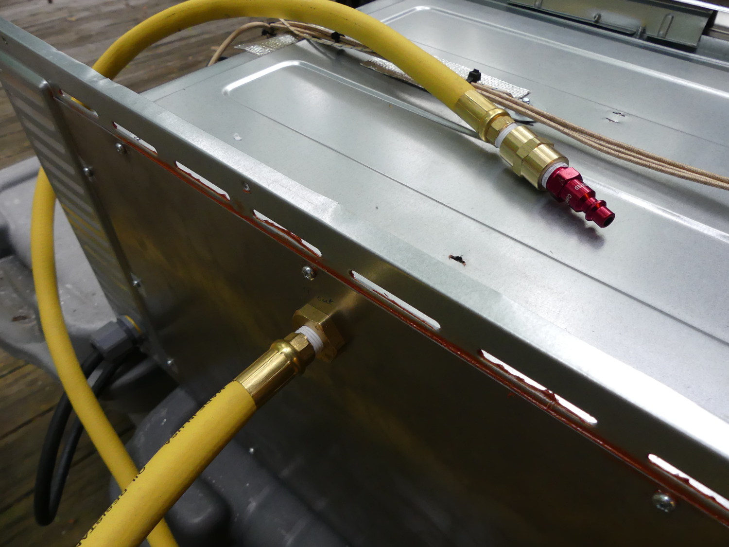 I have a quick disconnect attached to the high pressure regulator on my nitrogen bottle, so I placed the mating connector on a six foot section of quality Goodyear low pressure hose and then threaded that into a bulkhead connector I installed on the rear bulkhead of the oven. |
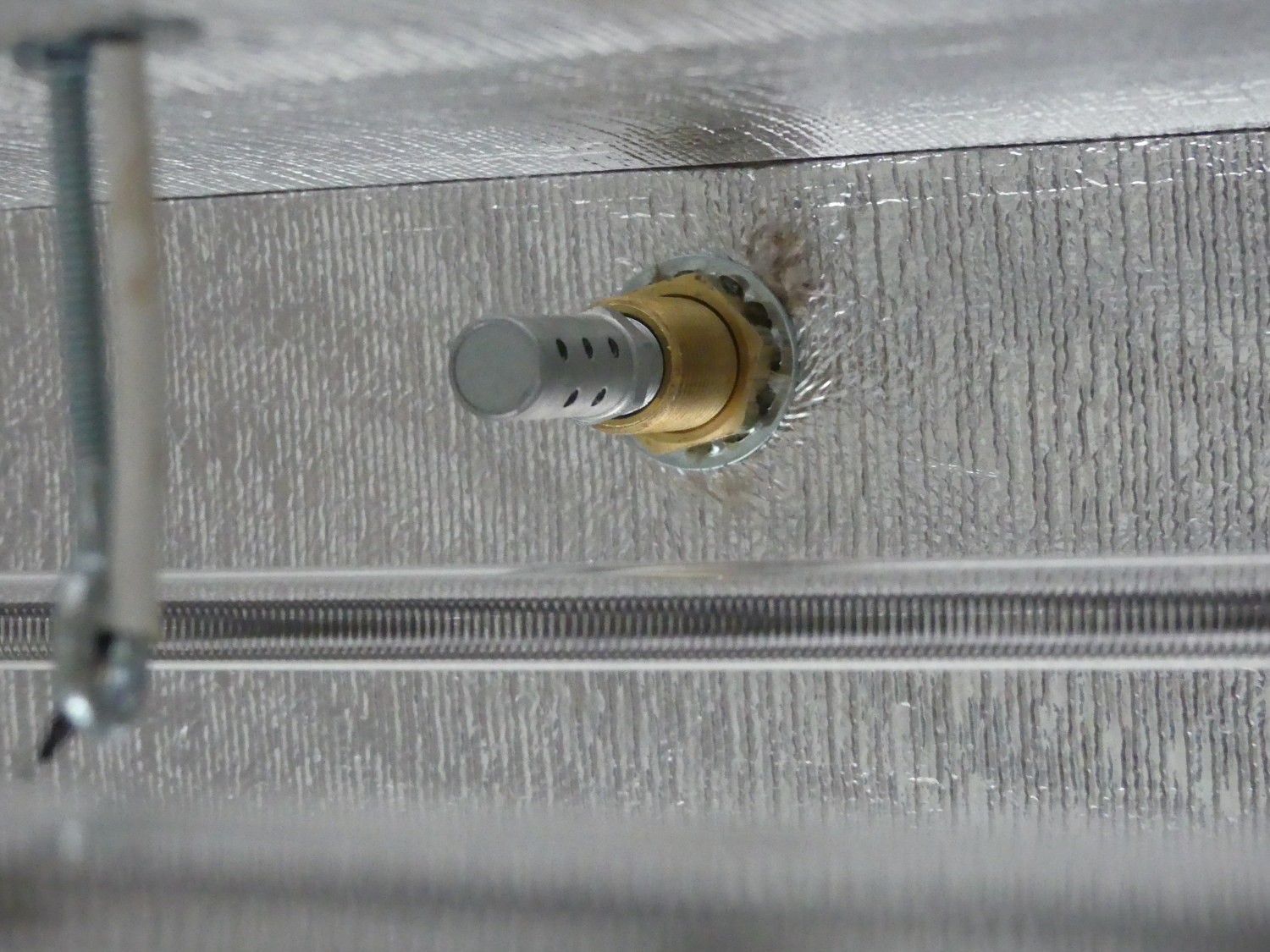 A closeup showing the bulkhead fitting penetration inside the oven. Note that this fitting is threaded both on the outside (for the retaining nut) and inside with 1/4 inch NPT threads suitable for the muffler. Note that the inside of the muffler is lined with screen to further diffuse the nitrogen as it exits. |
While removing the remaining insulation I found the glue that remained protected under the other strips peeled off the ceiling pretty easily but the glue that melted under reflow was quite stubborn. A combination of a razor-blade scraper and some goo-gone were necessary to remove it. I then cleaned up with 99% IPA and that did its part as well to remove the remaining residue and eliminate the oily film left behind by the goo-gone. To wrap things up I also used the 99% IPA to clean the surface of the remaining insulation and used the Gold reflective tape Peter provided in the kit to seal most of the seams I had seen lifting previously.
I'm still not particularly confident the remaining insulation will hold up, but I just need the oven to survive another couple dozen reflow cycles before I go to production and give this thankless job to the professionals and their $100K reflow ovens.
Nitrogen Inerting
The Ultimus I needs a source of clean, dry air to remain in compliance with the warranty requirements. Given that I can't run a noisy compressor, I purchased a Nitrogen cylinder and the high pressure regulator needed to reduce it to a working pressure. I quickly realized that the apparatus could serve double duty with the reflow oven for inerting so I bought a few extra parts to connect the tank to the oven and installed them. This was a surprisingly easy upgrade involving a quick disconnect fitting for connection to the regulator, a six foot length of low pressure hose, a bulkhead fitting, and a diffuser / muffler I added mostly as a failsafe in the event I increased the flow too rapidly.
I've only done a couple cycles with the nitrogen connected and I've noticed a slightly brighter solder finish (less oxidation) after cleaning. I am also hoping that this will make the flux more effective and reduce the liklihood of bridging of some lower pitch parts such as 0.5mm LQFPs but as of this writing I haven't had a chance to assemble the related boards yet.
Videos
I produced two videos during this project. The first outlines the design choices and parts selection, while the second shows the completed oven and some of the issues I experienced.