


BMW E36 M52 (6 Cylinder)
Idle Control Valve and Crankcase Vent DIY
Failure modes for the idle control valve and crankcase vent aren't pretty.
Fortunately, however,
replacement of these parts shares a common labor sequence outlined here.
Introduction
This DIY outlines the labor required to replace three functionally separate parts, the idle control valve (ICV), crankcase vent (CCV), and intake manifold air temperature sensor, which are defined as follows:
- Idle Control Valve (ICV) - This is essentially a low-flow, high precision throttle body that provides fine grained control of the engine below approximately 20% throttle.
- Crankcase Vent (CCV) - The crankcase vent is an oil separator that ensures oil mist generated in the normal functioning of the engine finds its way from the top of the engine back to the oil sump.
- Intake Air Temperature Sensor - This sensor is used by the DME to determine the temperature of the air entering the manifold via the throttle body.
The procedure required to gain access to these parts is quite similar, hence they are combined into this single DIY. This procedure is applicable to the E36's M52 6 cylinder engine.
Troubleshooting
The ICV can become clogged with carbon deposits and fail to open and close smoothly. If this occurs the idle may oscillate. During more radical oscillations the engine can die. Unfortunately, these symptoms are also typical of vacuum leaks so in the event you lack access to a GT1 analyzer for a proper diagnosis the ICV should not be replaced until vacuum leaks have been eliminated as a possible cause. If the ICV is believed to be the cause it can be removed and cleaned with a toothbrush and a good amount of throttle body or carb cleaner.
The ICV can also stop functioning due to sudden failure of the integral electric motor. When this occurs the throttle will operate like a dead man's switch, i.e. the throttle must be kept open with a constant pressure on the accelerator pedal to keep the engine running; if pressure is released from the pedal the engine will die. This can be downright dangerous in an automobile that relies on an engine driven pump to provide power assisted steering and engine vacuum to augment brake operation. If this failure mode occurs, DO NOT DRIVE THE CAR until it is fixed as the risk of losing the ability to steer the car is too great, even if you think you're slick and skilled in heel-toe technique.
The CCV also has two failure modes. The most serious failure mode occurs during sub-freezing temperatures and is the result of a mixture of oil mist and condensate (water) combining and freezing the separator solid so it can't do it's job. In the other failure mode the integral diaphragm in the CCV cracks and creates both a vacuum leak and a path for oil vapor to be sucked into the intake manifold and later burned. The result is usually a rough running engine and lots of blue smoke billowing from the exhaust. If this occurs it will most likely be associated with a check engine light (CEL) due to the vacuum leak and misfires that are the result of the contaminated fuel mixture. In a worst case scenario, if sufficient oil is sucked into the manifold the result can be a hydrolocked engine and a very large repair bill. For this reason I believe replacement of the $80 CCV is cheap insurance while you are under the hood to replace the ICV.
There is only one failure mode of the temperature sensor and that would be flagged by the DME. Replacement of this sensor is optional but recommended while the throttle bodies are removed for other purposes.
Maintenance Schedule
For preventative maintenance purposes the ICV should be inspected and cleaned (or replaced) every 108K miles. The crankcase vent should be replaced at every 144K miles assuming frequent (5000 mile) oil changes. If you tend to leave the oil in the engine for much longer intervals I recommend replacement of the CCV at the same time the fuel preparation system is dismantled to clean / replace the ICV.
Prerequisites
Tools
- 10mm deep socket and accompanying ratchet (I used a 3/8 " drive unit)
- Appropriate safety equipment (Gloves and eye protection at a minimum)
Parts
- Idle Control Valve - 13411744713 (if appropriate to task)
- Crankcase Vent - 11151703484 (if appropriate to task)
- Throttle body to intake manifold profile gasket (optional)
- Throttle body to ASC throttle body mating gasket (optional, but recommended)
- Hose that connects the fuel tank breather valve to the manifold (optional, but highly recommended)
- Rubber hose that connects CCV to oil dipstick tube (CCV task only)
- Plastic hose that connects CCV to valve cover (CCV task only)
Part Highlights
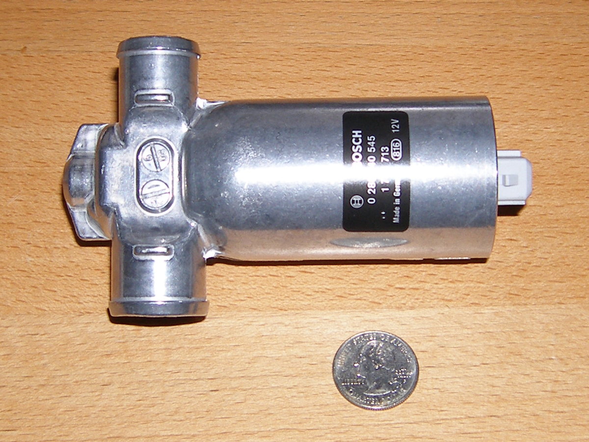 The Idle Control Valve is effectively an electromechanical throttle body that meters air below 20% throttle. |
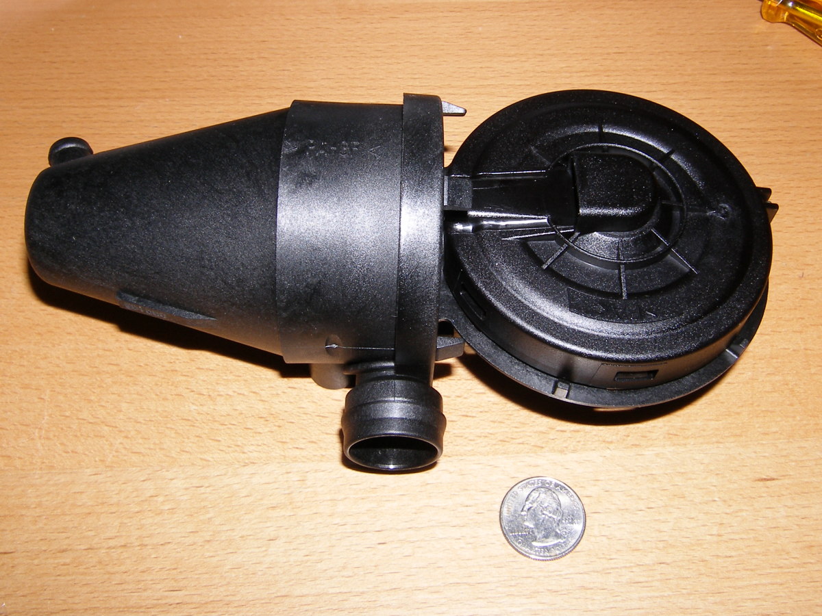 The Crankcase Vent (CCV) allows oil mist to condense and drain back into the sump via the oil dipstick. |
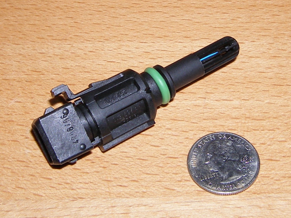 The DME measures intake air temperature using this sensor. Replacement is entirely optional, but convenient while the throttle bodies are removed. |
Removal / Disassembly Procedure
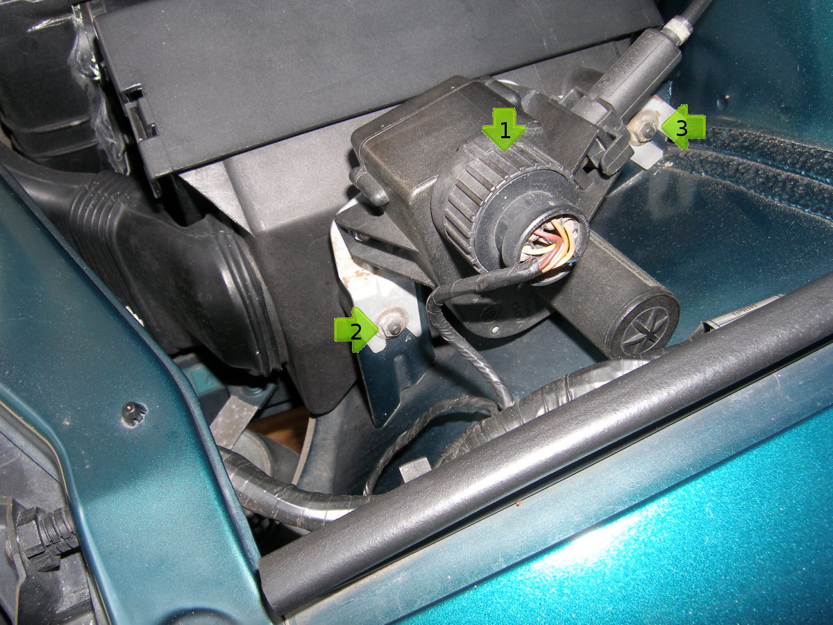
- Remove the cruise control unit. Remove the electrical connector from the cruise control unit by twisting the outer body of the connector counterclockwise 180 degrees and then pull to remove it. There are two (2) 10 mm nuts with captive washers that serve double duty -- they fasten both the cruise control unit and the airbox to the vehicle. Remove those nuts and then carefully fold the cruise control unit back over the shock tower to a point near the fuse box. It will stay there for the remainder of the procedure. No further disassembly is required.
- Remove the airbox by disconnecting the captive clips connecting it's outlet tube to the mass airflow sensor (MAF). Being careful not to misplace the large o-ring that mates the outlet tube and MAF, pull the box forward and then upward and out of the vehicle. Set it aside somewhere safe.
- Remove the mass airflow sensor. This is accomplished by first disconnecting the electrical connector by twisting the connector body counterclockwise approximately 180 degrees and then pulling the connector out of the mating connector on the MAF body. Second, loosen the large metal hose clamp that secures the MAF to the rubber intake boot. Carefully pull the MAF from the intake boot. Keep in mind that the MAF is an extremely expensive component so be sure to handle it with care and set it aside somewhere safe.
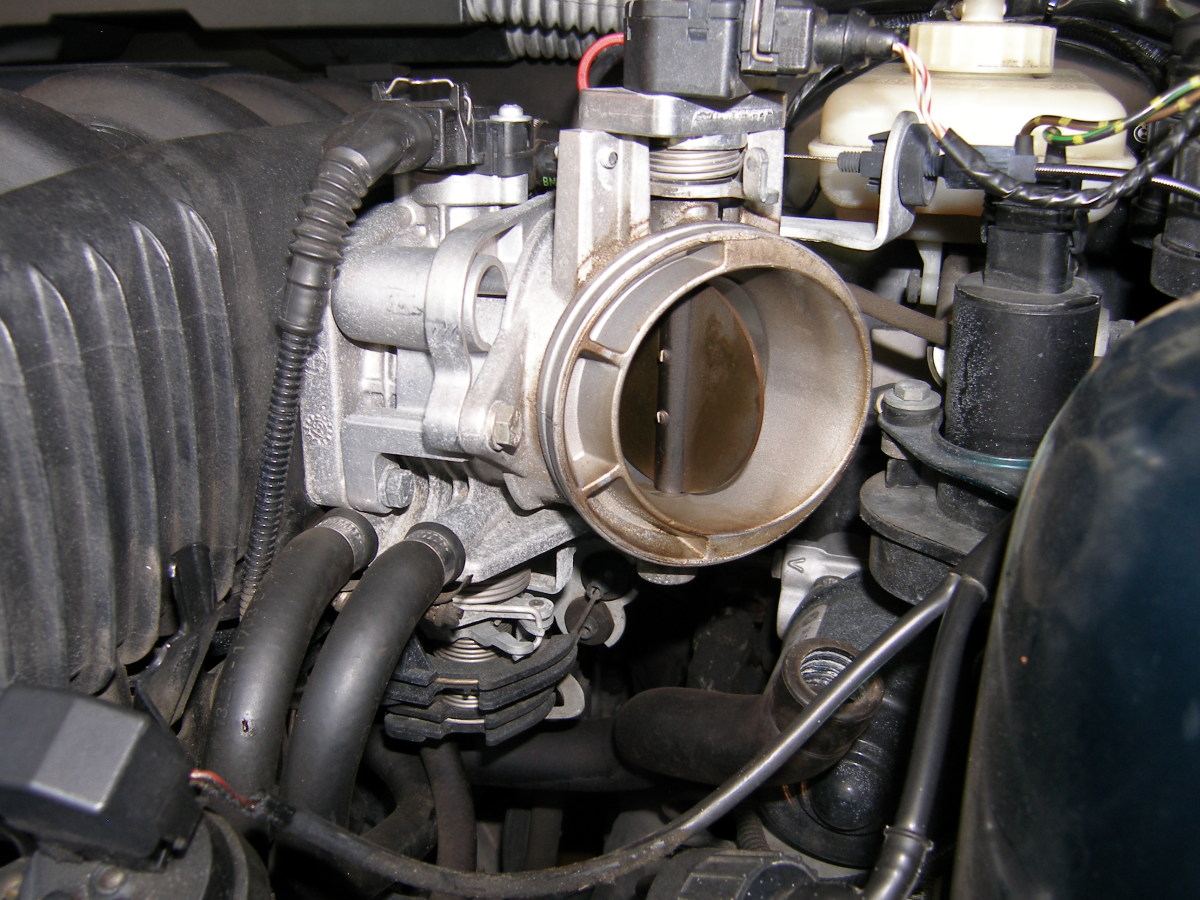
- Remove the intake boot. Loosen the large hose clamp fastening the boot to the main throttle body. Before you remove the boot, disconnect the hose that leads from to the bottom of the boot to the ICV. Note that this hose is fastened to the boot with an aggressive barb connector and it will require considerable force to remove. However, if you do not have a spare boot available I strongly advise you to be careful with it as these boots tend to develop cracks, particularly if they are old or original parts. If the boot develops even a hairline crack the car will run poorly due to the inrush of unmetered air.
- Remove the ASC throttle body (if equipped) from the main throttle body. Use a deep socket or shallow socket with a short extension to remove the two (2) 10 mm bolts. Carefully pull the throttle body back and out of the way. Once the ASC throttle body is removed, take note of the black rubber sealing ring which should be attached to the main throttle body. Replacement of the black sealing ring is optional, but recommended while you have the opportunity.
- Remove the main throttle body from the intake manifold. Use a deep socket or shallow socket with a short extension to remove the four bolts. The throttle body is heated using engine coolant to prevent ice from forming in the venturi so there are two 1/2" coolant hoses connected to it. You do not need to disconnect these hoses and in fact I do not recommend that you do so unless you happen to be doing this at the same time as a coolant flush. Once the throttle body is removed take note of the orange sealing ring that fits into a groove in the manifold. Make sure that is not misplaced or forgotten during reassembly.
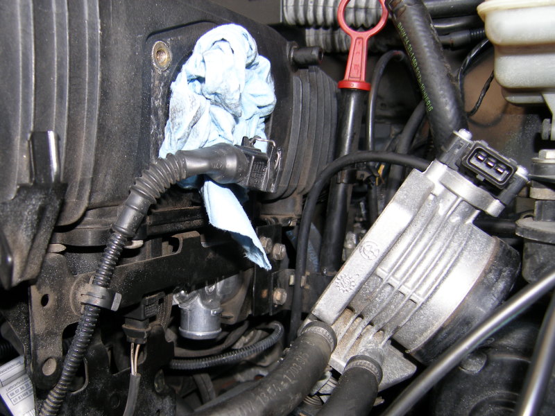
- Remove the ICV (if appropriate). Remove the three (3) 10 mm bolts that secure the oil dipstick tube and ICV mounting bracket to the engine. The bracket will come out connected to the ICV. Take note of the orientation of the ICV and the bracket for later reinstallation. I also recommend replacement of the hose that connects the intake boot to the ICV at this time simply because the hose is critical to the operation of the vehicle. The hose on my car was in relatively good shape though the ends were somewhat deformed.
- Remove the CCV (if appropriate). Remove the hoses leading from the CCV to both the intake manifold and the oil dipstick tube. To remove the CCV from the vehicle remove the three (3) 10 mm bolts that secure the CCV to the engine, pull the top of the part toward the cylinder head to remove it from the manifold. Lastly, extract it by tilting it horizontally and pulling it out from under the manifold. Note: you will need to remove the alternator cooling air duct for clearance.
Installation / Reassembly Procedure
- Clean the interior of both throttle bodies using throttle body or brake cleaner and lint free towels. Some of the dirt I found was difficult to remove which explains why I tried both throttle body and brake cleaner. As it turned out, elbow grease turned out to be most effective means of removing it. Note that you might be tempted to stick something like a screwdriver through the throttle body to keep the spring-loaded throttle plate open as you clean but I strongly advise against that because it may cause damage to the throttle plate and affect the sealing effect of the plate. Simply hold it open with one hand as you clean with the other. It sounds difficult, but it's not.
- Install new ICV (if appropriate). The bolts that fasten the ICV bracket to the engine are tightened by feel, but if you're looking for a torque value I'd say not more then 10 ft-lbs based strictly on the size of the bolt.
- Install new CCV (if appropriate). Insert the gray intake manifold grommet onto the CCV and then insert the CCV into the manifold. Reconnect the hoses, and then secure the CCV to the engine with the three bolts.
- Reinstall the throttle bodies. Tighten the bolts by feel or to 10 ft*lbs. Don't forget both sealing gaskets.
- Reinstall the intake boot and make sure the hose leading to the ICV is properly connected. Due to the nature of the barb connector, if you have a new hose in particular it will be somewhat difficult to full seat it, but it must be properly installed to prevent a vacuum leak. Do not over tighten the hose clamp securing the boot. Just make sure that the boot will not come off with a good tug.
- Conduct a reassembly inspection to make sure all electrical connectors and hoses have been properly connected before proceeding. Now is the time to do this because the area will not be visible once the MAF and airbox are reinstalled.
- Reinstall mass airflow sensor.
- Reinstall airbox and cruise control unit.
- Start the engine to test your work.
Procedure Highlights
 Begin by disconnecting the cruise control wiring connector (1) and then the two 10 mm nuts with captive washers that retain both the cruise control unit and the airbox (2 and 3). |
 After disconnecting the cruise control unit fold it back toward the fuse panel. |
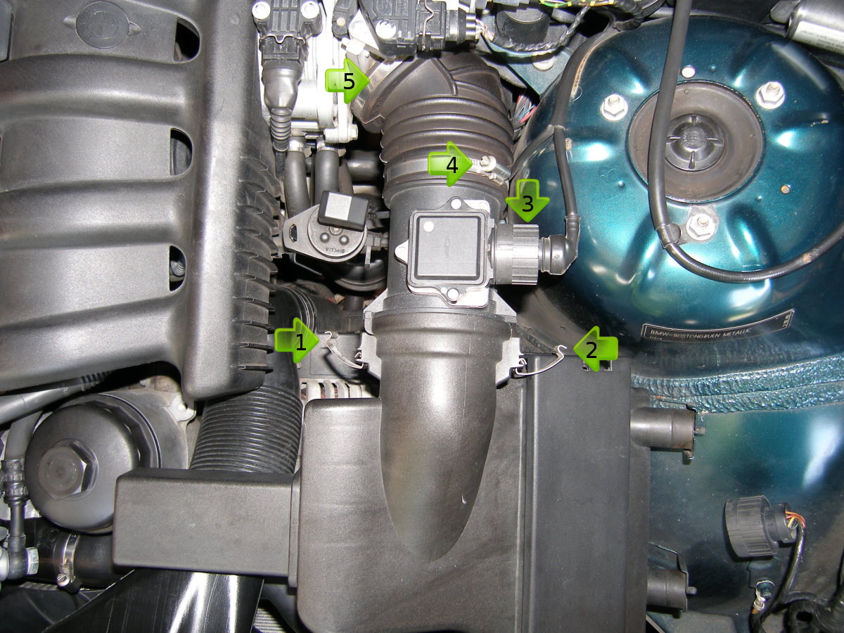 This is a top-down look at the M52 fuel preparation system. Arrows: Airbox clips (1) and (2), MAF connector, and intake boot retaining clamps (4) and (5). |
 Just an orientation shot with the airbox remove. Note that we have yet to remove the alternator cooling duct as required to reach the CCV. |
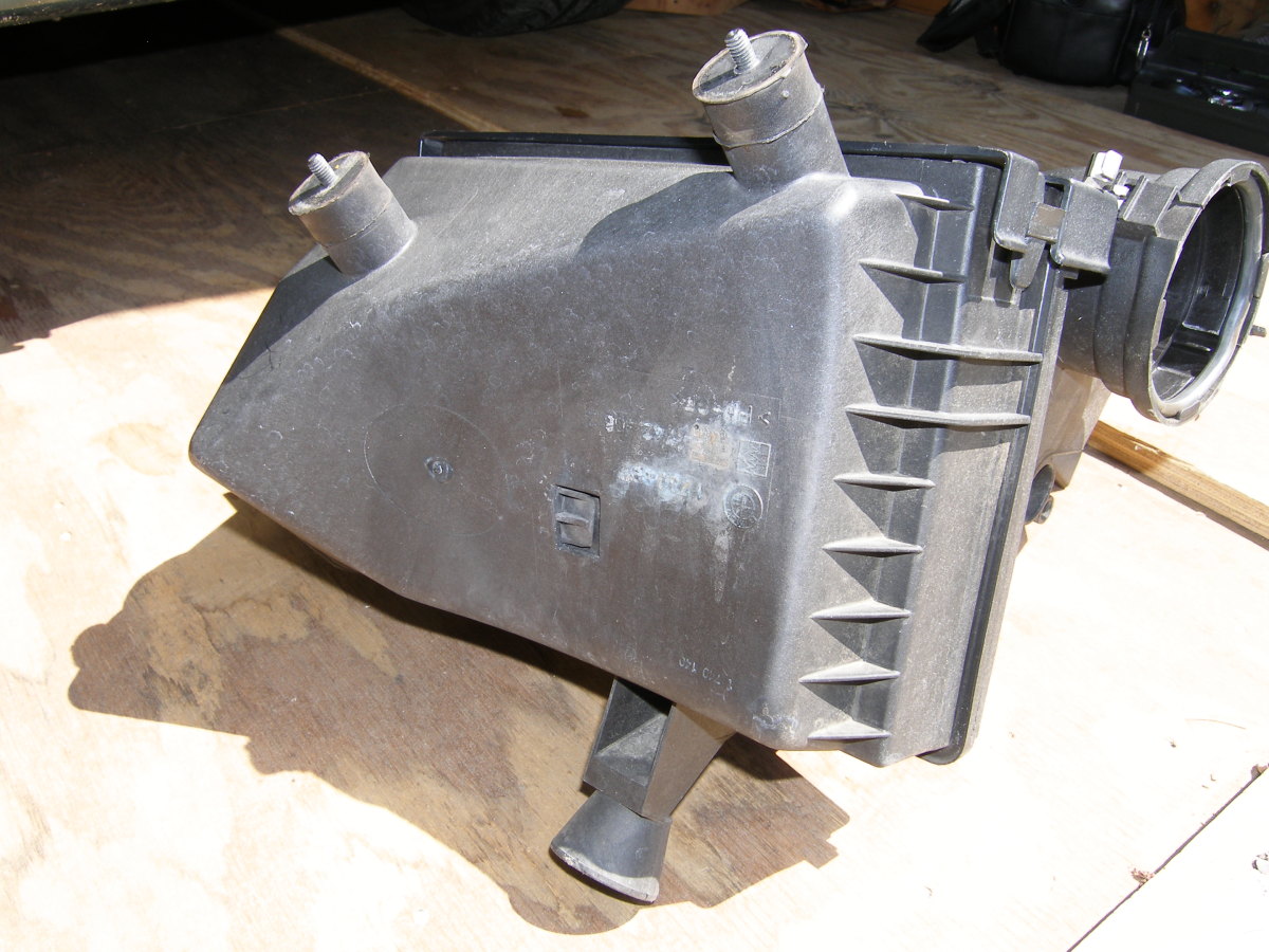 This shot of the rear of the airbox shows that the bottom simply rests on a pivot point on the body under its own weight. Only two nuts hold the airbox to the car. |
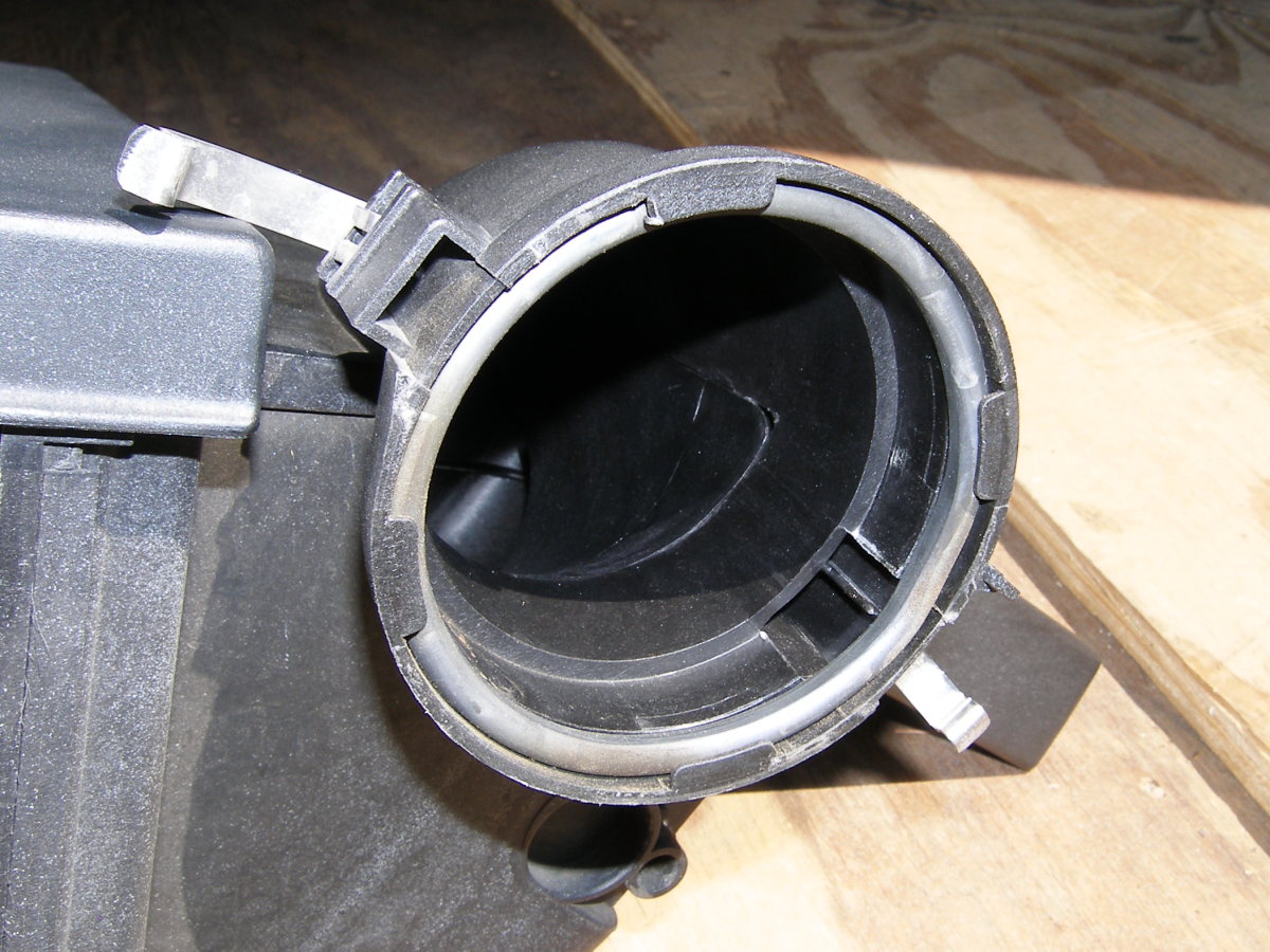 A closeup of the large o-ring that seals the connection between the airbox and MAF. Don't lose this! |
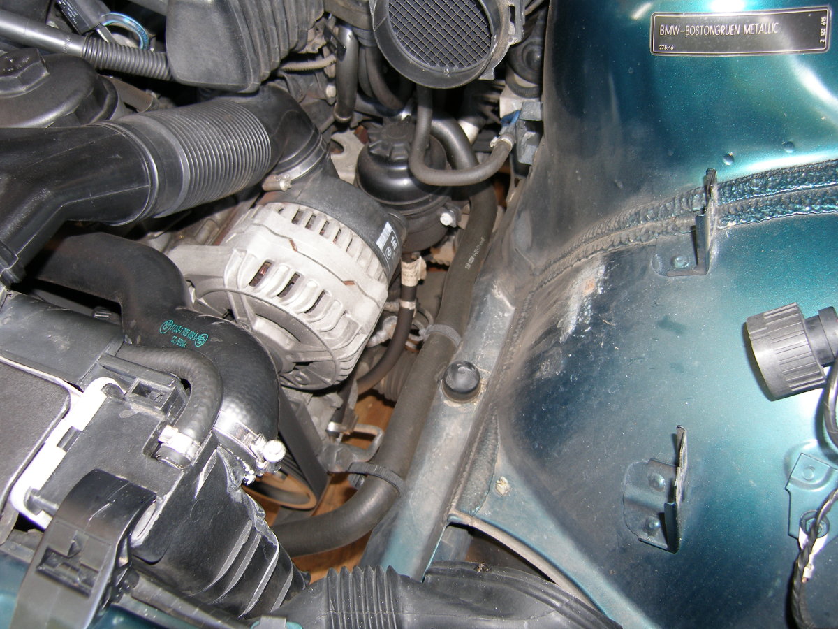
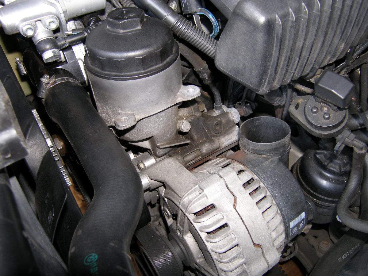 Another orientation shot showing the alternator cooling duct removed. The hose in the upper center of this view connects the valve cover to the CCV. Follow this to find the CCV. |
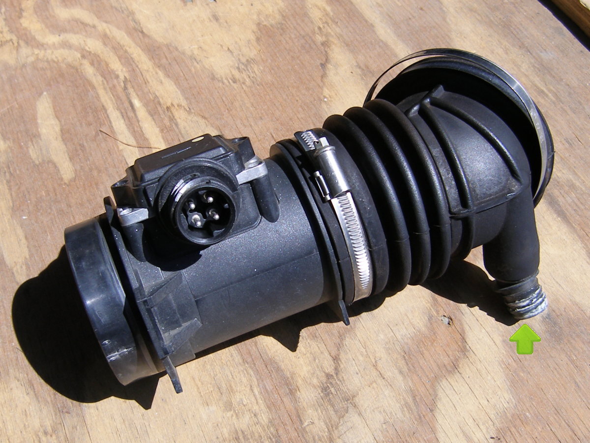 A closeup of the MAF. The hose that leads to the ICV connects to the barbed connector highlighted with the arrow. |
 The ASC (traction control) throttle body is controlled by the DME and is used to reduce throttle and eliminate wheel spin. With the intake boot disconnected, remove the electrical connector and the two retaining bolts, then remove the throttle body. |
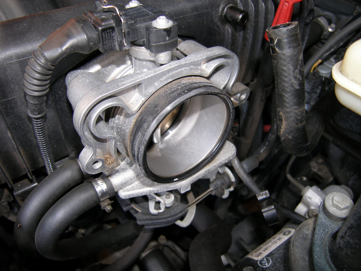 With the ASC throttle body removed you can see the main throttle body and the black sealing ring. I recommend replacing that while you're in here Leave the coolant lines connected. |
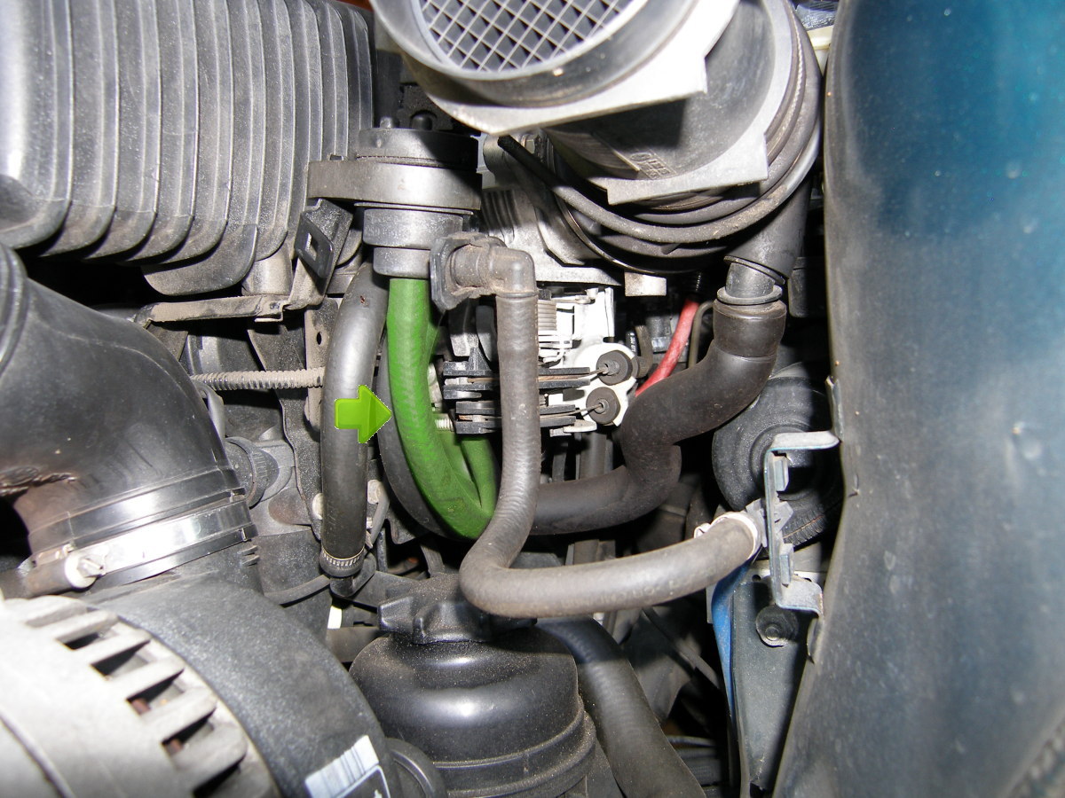 One gotcha. The hose highlighted in green connects to the intake manifold. If it comes off during this procedure, it helps to have a mirror to find the nipple on the manifold. |
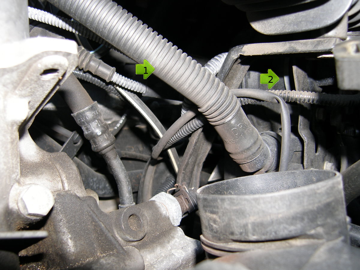 This view is taken of the front of the manifold just above the alternator looking backward. The hose connecting the valve cover and CCV (1) will lead you right to the CCV, which connects to the underside of the manifold (2). |
 Remember to clean up the throttle body while you have it apart. Mine was pretty clean given the mileage, but I found some stubborn grime around the throttle plate. |
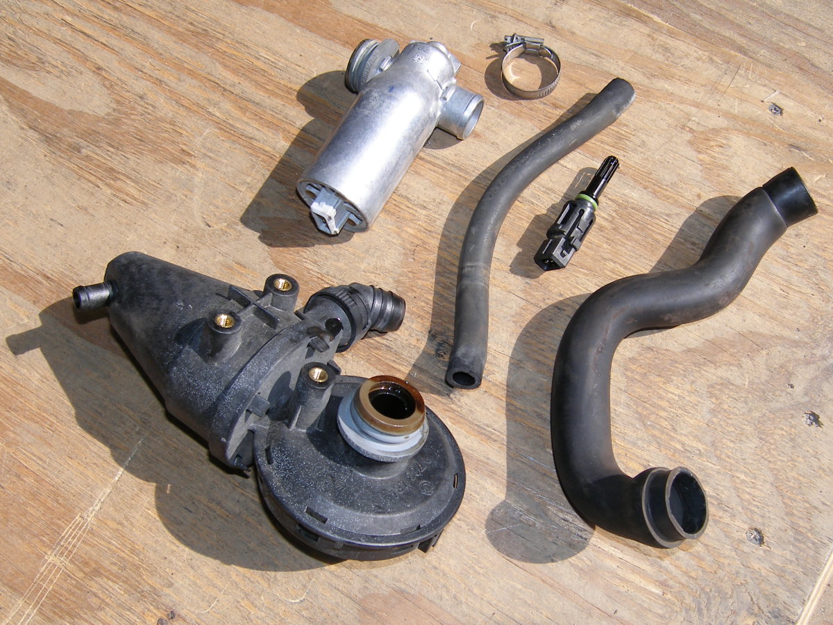 What you should have after completing this job assuming you replace the CCV, ICV and temperature sensor. |
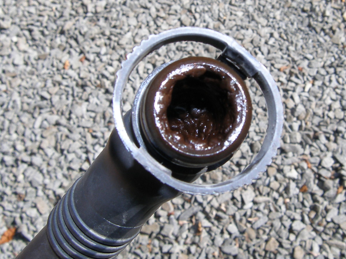 This is why you should replace the hose that connects the valve cover to the CCV. |
Conclusion
Replacement of the ICV and CCV are pretty rare events on the E36's M52 engine but they are important for the long term health of the engine. I recommend the units be replaced before they fail simply because the failure modes can be annoying and potentially expensive.
I neglected to buy the black rubber sealing ring that mates the ASC and main throttle body. Based on its age and condition I probably should have replaced it. The orange sealing ring, on the other hand, could have been reused yet I replaced it anyway because I had it on hand. If you have to replace just one sealing ring, make sure it's the black one.
I recommend replacement of the hose that connects the CCV to the dipstick tube. I found mine hardened to the point that I had to use a utility knife to remove it from the tube. I also recommend replacement of the plastic hose that connects the ICV to the valve cover because mine was brittle and broke apart at the fitting when I attempted to separate it from the CCV. The interior diameter of the hose was also reduced by the accretions of oil residue.
I experienced two snags during this job. The first snag occurred during an inspection I conducted just before I reinstalled the MAF and airbox. I noticed the hose connected to the fuel tank breather valve (the unit mounted to the side of the manifold via a rubber isolation mount) was not connected to anything. I did not see it come loose so I had no idea where it should be connected. Thanks in part to the photos I took for this DIY I found an open barbed nipple on the underside of the manifold just aft of where the CCV mounts. I reinstalled the hose and found it mated with the nipple as expected. The point to take away from this is that the hose was hardened due to age and did not fit tightly to the nipple on the manifold. That explains why it came off quickly and silently as I moved the breather valve around for clearance. I strongly advise this hose be replaced simply to make sure it fits tightly with the manifold.
The second snag had to do with replacement of the intake air temperature sensor that I replaced while I had everything apart (and for $20, who could blame me). The connector for this sensor faces upward and mates with the sensor vertically under the intake manifold. This makes it possible (however unlikely) that water might enter the connector. For this reason, the connector has a high quality seal that I can only describe as a rectangular foam o-ring. After I finished the job and moved the car out of the garage I noticed one such seal on the floor of the garage and I had no idea initially where it came from. After some thought and a process of elimination I realized the size of the seal matched that of the air temperature sensor. The seal apparently stuck to the sensor as I pulled the connector off and then it dropped down through the engine bay and onto the floor while I wasn't looking. Needless to say, I had to remove the airbox again to replace it. Avoid this extra work and make sure any and all electrical connector seals are reinstalled properly.