


Sunday, February 4, 2024
Revision 9
In the last month I've had a single email conversation with my architect, though she hasn't officially started the project yet. She asked if I had any updates and I sent her some of the design tweaks I'd been working on, leading me to conclude one of my emails with "I can build anything, but I won't build something ugly". She seemed somewhat relieved with that admission and I sent her copies of the changes that I think at least partially achieve this goal.
As the building has grown in size and become essentially a large rectangular box similar in appearance to my brother's 3200 square foot toybox, I felt I needed to add some additional dimensions to the structure to make it look more like a house and less like a warehouse, as well as visually separate the workshop and the garage so we could use different design elements / materials / colors on each, but that's easier said than done, particularly on a budget.
The problem is, every turn in a structure's layout adds complexity and cost, both to the foundation and the structure above it, including the roof, so I had to temper my changes to avoid creating something needlessly complex or difficult to frame. The solution I designed essentially shrinks the front to back dimension of the center of the structure, creating a dog-bone-like footprint and a connector between the workshop and residence. This is a concept I considered when I designed the post and beam home, though in that case the garage and residence were offset from one another. This is what I'm calling Revision 9.
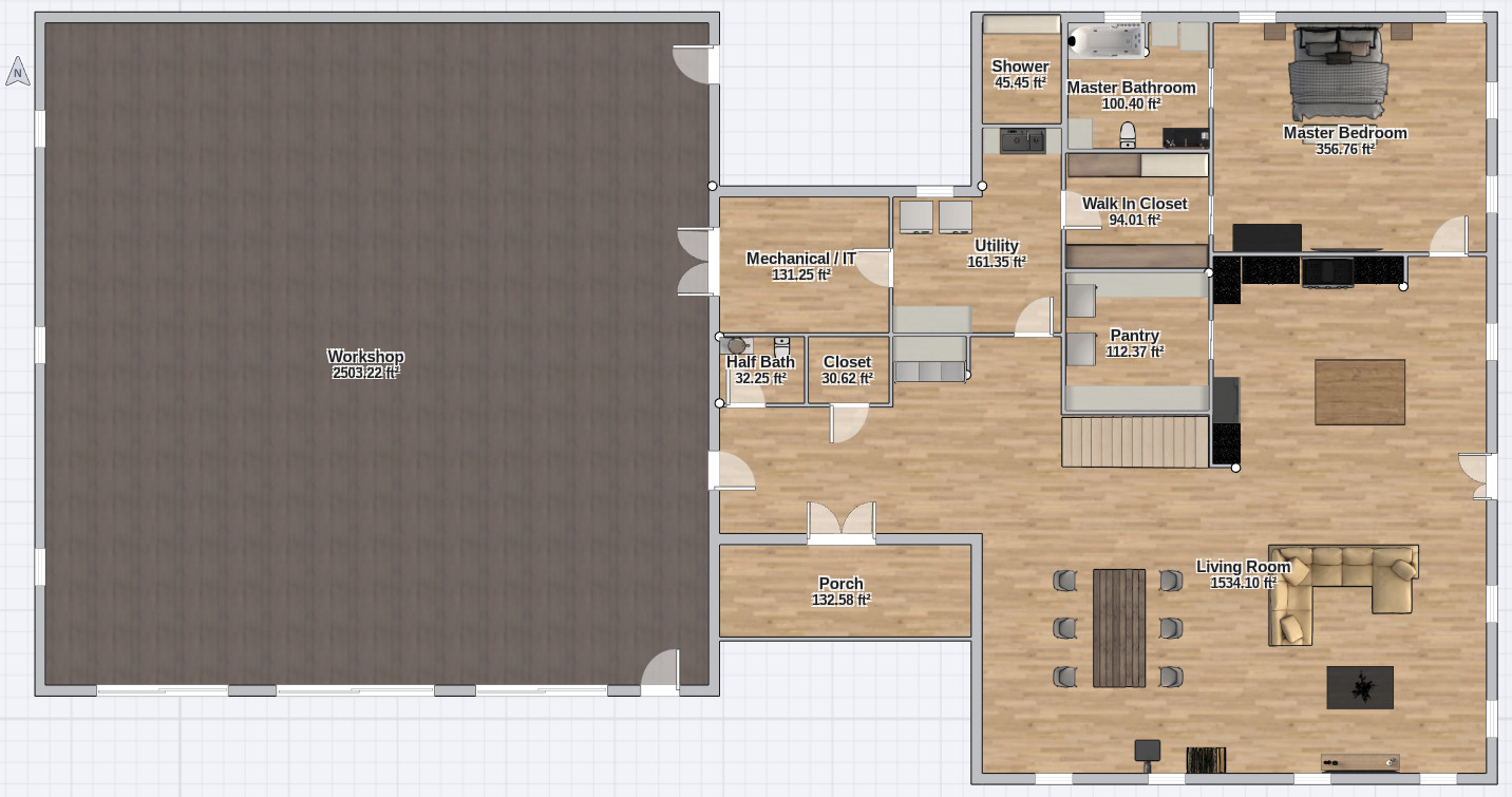
Key elements in this floorplan are:
-
The connector reduces the overall width of the residence slightly, while allowing a slight increase in the width of the master bedroom / kitchen / living room area. Both the roof and floor truss spans will be shorter, and the shorter floor trusses should make it easier to build the floor to a L/480 or even a L/720 deflection standard.
-
I've added a covered porch to serve as the formal entry to the home, and we'll likely construct it of post-and-beam elements to better mesh with the mountain setting and the other structures I'm planning to build.
-
I've fixed an oversight in the location of the mechanical room, which now has an exterior-facing wall as needed to keep routing of refrigerant lines to the exterior HVAC equipment and other vents as short as possible.
-
The utility room still has an exterior wall as needed to give the dryer exhaust a short and direct path outside, and now the room is connected to the mechanical room as well.
-
The mechanical room and all other rooms that require plumbing are kept in close proximity to reduce water waste when supplying hot water and the overall cost of the required plumbing materials. In short, less pipe equals lower cost.
-
One compromise I've made is to combine the mechanical and IT rooms. As other areas of the home have increased in square footage I can't justify the space for a separate IT room, particularly given that I will likely have only one or two server racks for all of my equipment. The size of the mechanical room is now slightly bigger than in the prior design, but as I've eliminated the separate IT room the total square footage is less.
-
The mud room has expanded a bit into a larger entryway to make the home a bit more inviting. The closet and half bath remain accessible near both the door leading to the workshop as well as the front door, as required to minimize the impact of any dirt tracked into the home, should I be working outside (or in the workshop) and require a quick bathroom break.
-
I've added a door on the right side of the residence to allow easier access to the wood shed I plan to put behind the structure and to provide access to a covered area I plan to integrate with the design to include outdoor seating and a grill.
Roof Design Changes
When this structure started out as a simple 40x40 utility building I had plans for a roof structure where the ridge spanned the full width of the building and the gable ends were on the left and right sides. The goal was to provide a lot of south-facing roof area on which I could install a solar array.
The new footprint I created naturally lent itself to three separate roof assemblies, one each for the workshop, connector, and residence. The ridge lines of the workshop and residence will now run from the front to the rear of the structure to allow for windows to be installed in the upper gable end of the structure for a southern exposure and promote natural light within both buildings, while the connector roof will retain the left-right ridge line and intersect with the other roof assemblies.
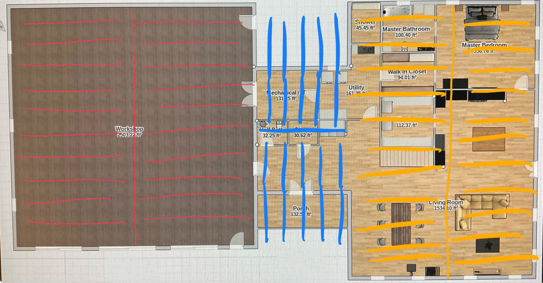
The perks of this change will allow me to install south-facing windows in the gable end of the structures, allowing an increase in natural light. And, in the case of the workshop, should we decide to utilize scissor trusses, I would be able to reduce the overall height of the walls and have the center bay provide the highest ceiling height for maintenance of vehicles or the storage of larger heavy equipment.
The unfortunate consequence of this change is a significant decrease of the roof area facing due south, which means fewer solar panels may be installed in the optimum location. But as I said earlier, my goal was never to put a huge solar array on any single building -- it was to install an array capable of charging a small battery bank during a normal sunny day, and I think I can fit the ideal solar capacity on the south-facing connector roof. Should I need additional capacity, it's safe to say that modern monocrystalline panels are to some degree less dependent on direct sun and may be installed on the other roof panels with a modest decrease in solar production efficiency as the sun scribes its daily arc across the sky.
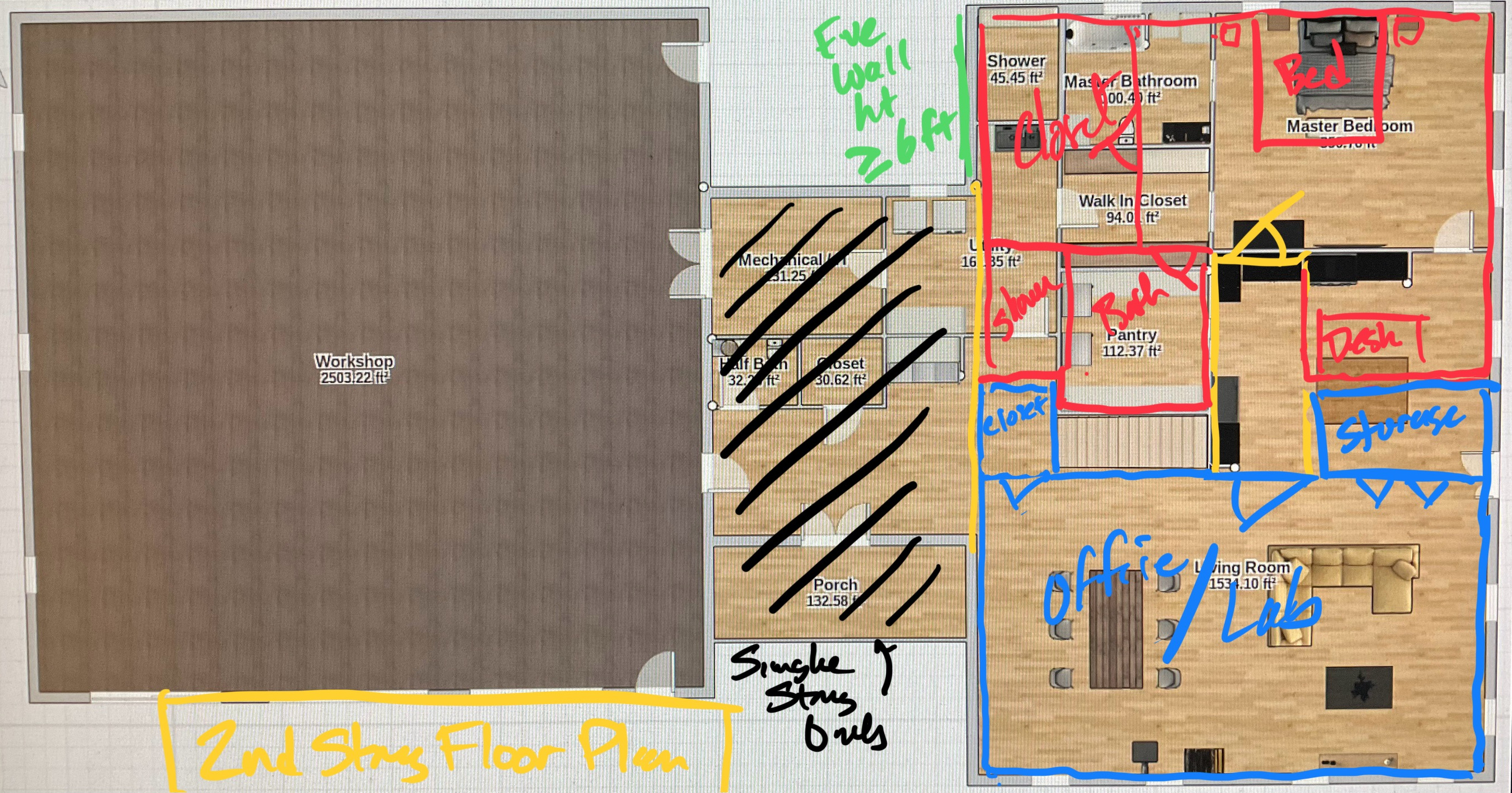
Second Floor Plan
Using the first floor plan and its implied structural elements as a guide, I've come up with an early concept for the second floor of the residence. The goal of the second floor is to host a guest suite and a large office / lab space area I'll use for my business. Initially I foresee the lab being entirely open space, but I can always frame in a wall or two as my needs (and noise levels in the lab space) change.
Monopoly Framing
I'm considering "Monopoly Framing" the structure. This relatively modern framing technique gets its name from the observation that the resulting structure looks like a playing piece from the board game. Rather than integrating rafter tails into the roof structure, around which the side wall sheathing must be intricately cut and sealed, the structure utilizes heel trusses for the roof and then runs the side wall sheathing straight up over the heel of the truss to where it intersects with the roof sheathing. This makes it extremely easy to insulate and air seal the structure. This also very securely ties the roof assembly to the underlying structure, which is of concern in a high wind environment. I'll probably still specify some sort of hurricane tie or structural screws between the top plate and each truss, but with this framing technique they'll be filed under the heading of "belt and suspenders".
The downside to monopoly framing is that the overhangs must be framed independently and affixed to the upper portion of the sidewall to continue the roofline and overhang accordingly. This downside is, in my opinion, far outweighed by the advantages, including the fact that these overhangs can be left open and constructed of more substantial timbers to provide the look of a timber frame, or closed in and conventionally framed with a soffit material. If closed in, the overhangs don't need to be insulated, as they are outside the conditioned envelope, and it's therefore very easy to route cables for lighting or surveillance equipment through them and then enter the conditioned envelope using a small number of easily-sealed holes in the sheathing inside the overhang, further reducing air infiltration. If you're wondering where I got the idea from, check out Matt Risinger's channel on YouTube. He didn't create the technique, but he was the first person I heard use the term.
Staggered Stud Walls
I am entertaining the idea of framing the exterior walls using staggered studs. In this framing technique the wall assembly is constructed of two sets of studs -- one aligned with the exterior face to accept the exterior sheathing and another set aligned with the interior face to accept drywall, with both mated to larger top and bottom plates and offset accordingly. The interior and exterior studs need not be of the same depth.
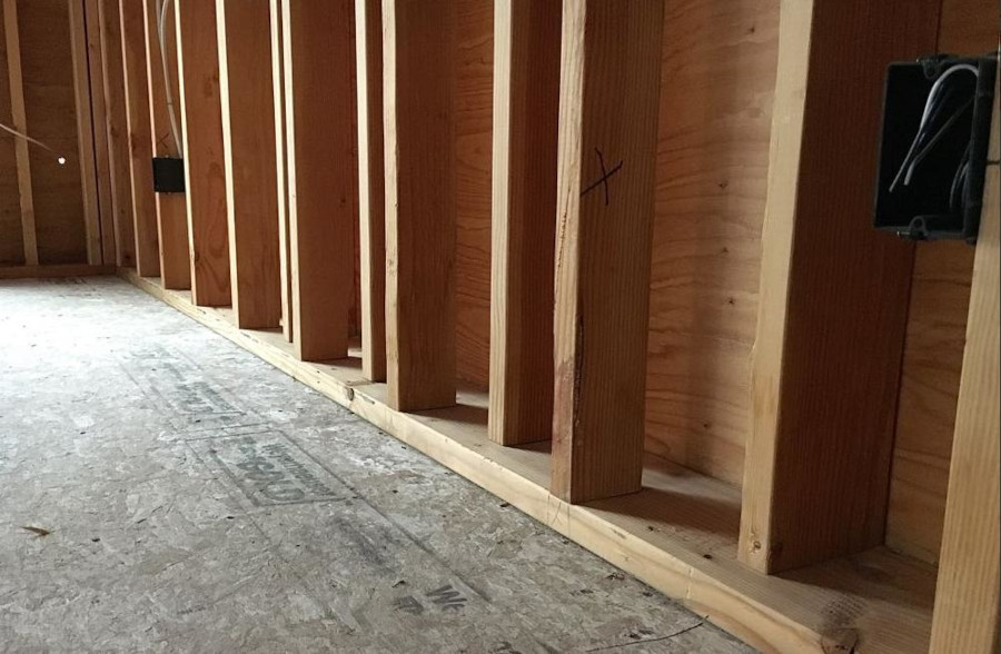
In my case a conventional 2x8 exterior wall would likely be required for structural reasons, but rather than use 2x8 top and bottom plates with 2x8 studs 16" on-center (OC), I can frame the exterior studs with 2x6 and the interior studs with 2x4. A wall assembly constructed of staggered studs should have several advantages:
-
The wall should be stronger than a conventionally framed 2x6 or 2x8 wall framed with studs 16" OC, both in terms of vertical loads and sheer loads due to the offset framing.
-
As the cost of lumber increases by some exponent relative to size, a set of 2x6 studs combined with a set of 2x4 should be cost-equivalent or perhaps slightly less than using 2x8 or 2x10 framing that is sometimes required to achieve energy efficiency with modern codes.
-
This will prevent thermal bridging, to the point that the finished wall assembly should easily meet my energy efficiency goals without exterior insulation. If you're wondering why I don't like exterior insulation, it's because there is more than enough evidence to suggest termites use it to tunnel despite various strategies to seal the bottom of the insulation.
-
I can use readily available mineral wool in R-23 bats in the exterior wall cavities and keep the interior wall assembly clear to make routing utilities easier.
The single biggest disadvantage I can see is related to insulation. A 2x10 plate would provide perfect clearance for an R-23 bat while not imposing on the 2x4 cavity, but the obvious downside would be the need for a wider foundation wall and the corresponding increase in concrete for it.
I'm also considering having the structure design sent to a prefab company so the exterior wall assemblies can be constructed in a factory then craned into place, but I would have to discuss this with my builder first, as some builders may be more comfortable and more cost efficient with conventional stick framing.