


Friday, August 2, 2013
Differential Fluid Service
It seemed like only yesterday I overhauled the rear end and had my local indy tech work over the differential. New fluid was part of that deal, of course, but that was 44K miles ago and 8K beyond my standard 36K mile service interval. When I drained the gear oil this time I found it to be amber in color and notably lower in viscosity than the new stuff. I don't know exactly what fluid Don used so I can't really judge the color, but I think it's safe to say the lower viscosity was related to age and perhaps heat -- I'd driven the car a couple hours that morning and even open rears heat up.
Audio System Engineering Update
After reading the user manuals and various white papers provided by Jensen Transformers I realized that I had two prepackaged line transformer options - the PI-2XX (“PI”) and the DM2-2XX (“DM2”) Another read of the documents prior to purchase highlighted some differences between the models and clarified a few things worthy of note.
First, the PI contains transformers that are wrapped in a steel can (effectively a Faraday shield) which provides excellent EMI protection. The DM2 contains a more traditional laminated core transformer with no shielding other than the case. This means the PI is better at rejecting interference, particularly at very high (radio) frequencies.
One downside to the PI is that it restricts output cable length (which is to say, the cable that connects the output of the isolator with the MiniDSP input) to less than three feet. The user manual goes on to suggest that two feet is a safe maximum and there is little point in reducing the length to less than 8 inches, but shorter is always better if high frequency audio response is to be preserved. Since I plan to co-locate the isolators and MiniDSPs I should be able to conform to this requirement.
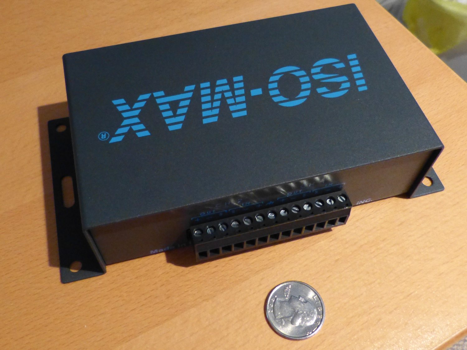 The rear panel of the PI-2XX is host to a removable terminal block that supports all connections. Use of the front panel XLR connectors is optional. |
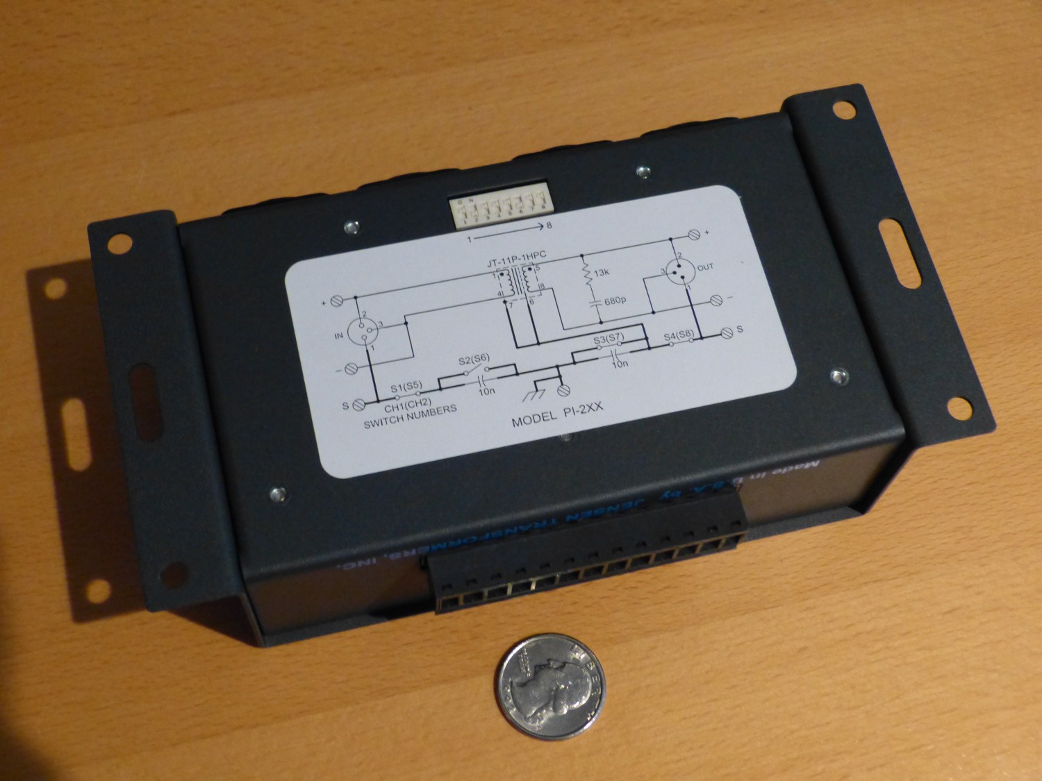 The bottom of the unit shows both the diagram and access to the DIP switches used to configure the device for the application. |
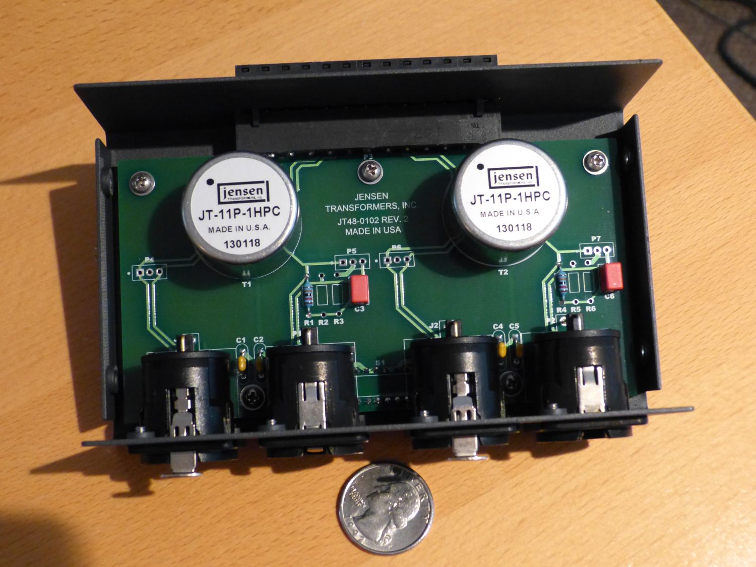 The cover removed shows the two transformer "cans" and some simple circuitry. I could built my own version but the boxed version was the best deal in terms of time and money. |
In addition to providing about 10 dB better CMRR in an ideal installation, the DM2 appears to tolerate a wider range of load impedances (600 Ohm to 10M Ohm) as compared to the PI (10K Ohm to 10M Ohm), though as expected the gain (loss, really) of the device suffers when loaded with 600 Ohms (-1.1dB) as opposed to something like 10K Ohms (-0.07 dB). The MiniDSP input impedance is not mentioned on the datasheet but a bit of searching the MiniDSP forums indicates that it's 47K Ohms. This means that either the PI or DM2 would work in my application and the losses should be minimal.
While the DM2 does not have the output cable length limitation of the PI and can therefore be placed anywhere in the line, it is best to insert this device at the driver end of the cable, which means close to the headunit. This may wind up being the deal breaker for the DM2, as I have no space to locate these devices there. I could, of course, split the difference and mount them on the rear deck behind each amp, but that's not the ideal solution.
The biggest revelation came while reading the user manuals and I'm surprised I missed it earlier. It's best to just quote it word for word:
Since ISO-MAX has truly floating inputs and outputs, it can be used to transfer signals from balanced outputs to unbalanced inputs or from unbalanced outputs to balanced inputs. When adapting cables are made, it is very important to use 3 conductors to avoid common-impedance noise coupling in the adapter cable. Wire the cables as shown below. Do not use commercial RCA to XLR adapters and ordinary single conductor shielded cables!
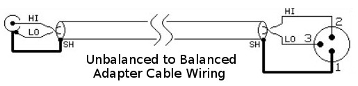
"Single conductor shielded cable" is of course the wordy definition of coaxial cable and "common-impedance noise coupling" is otherwise known as crosstalk. This means that I can use the same cable (Belden 8760) for all small-signal wiring, particularly between the headunit and the isolator where I previously assumed I would need to use traditional coax terminated with RCA connectors. This is a load off my mind, as this will lower the cost of wiring and make it easier to install because 8760 is less bulky, more flexible, and easier to terminate than a good quality coax.
The basic idea in the design of the "adapter cable" is this. At the headunit I'll tie the drain wire and one of the signal wires together and then connect them to the ring of the RCA connector which is connected to the ground of the headunit, while the other signal wire will naturally connect to the tip of the RCA connector. At the opposite end of the cable I'll connect all conductors to their respective points (+ / - / GND) on the input of the isolator. The signal output from the headunit will remain single-ended but the interface will still benefit from a reduction in crosstalk.
Generally speaking it's best to terminate the shield only on the driver side of a signal cable, which in the case of the adapter cable means the headunit. Even if I connect the drain wire to the GND terminal of the isolator's input, the PI and DM2 are equipped with jumpers that will allow me to lift or terminate the shield as desired. Although IEC standards suggest that in environments subject to RFI the shield should be terminated at the receiver end as well, in reality that can lead to ground loops and the related noise at audio frequencies.
The ideal solution therefore involves inserting an appropriately-sized capacitor in line with the drain wire where it connects to the receiver. The capacitor acts as a high pass filter (a short, really) at high frequencies and therefore shunts the RF current to ground as it should, while presenting a high impedance to low frequencies – the effective equivalent of leaving the drain wire disconnected. I'm not sure if I'll have to add a capacitor but if I do I'll likely buy an axial lead type, solder it at the end of drain wire and wrap the entire thing with heatshrink for a tidy appearance.
I ultimately bought the PI-2XX from Cable Solutions and plan to acquire the remaining components necessary to assemble and bench test the entire audio system to validate the design before I install it.
Mileage: 237635