


Thursday, June 12, 2014
Audio System Overhaul Update: MiniDSP and IsoMax Packaging
...the idea is to try to give all of the information to help others to judge the value of your contribution; not just the information that leads to judgment in one particular direction or another. – Richard Feynman
The stereo has been increasingly flaky over the last two years but all the problems have typically related to overdriving the amplifier during prolonged operation. The most recent episode was different in that it occurred first thing in the morning with the stereo “cold”. My initial observation was that the front right midrange and/or tweeter were not functioning and some basic troubleshooting with the balance and fader controls confirmed it. While the cause of the failure is unclear the event served to remind me of the need to package the MiniDC, MiniDSP, and IsoMax modules in prep for my stereo overhaul.
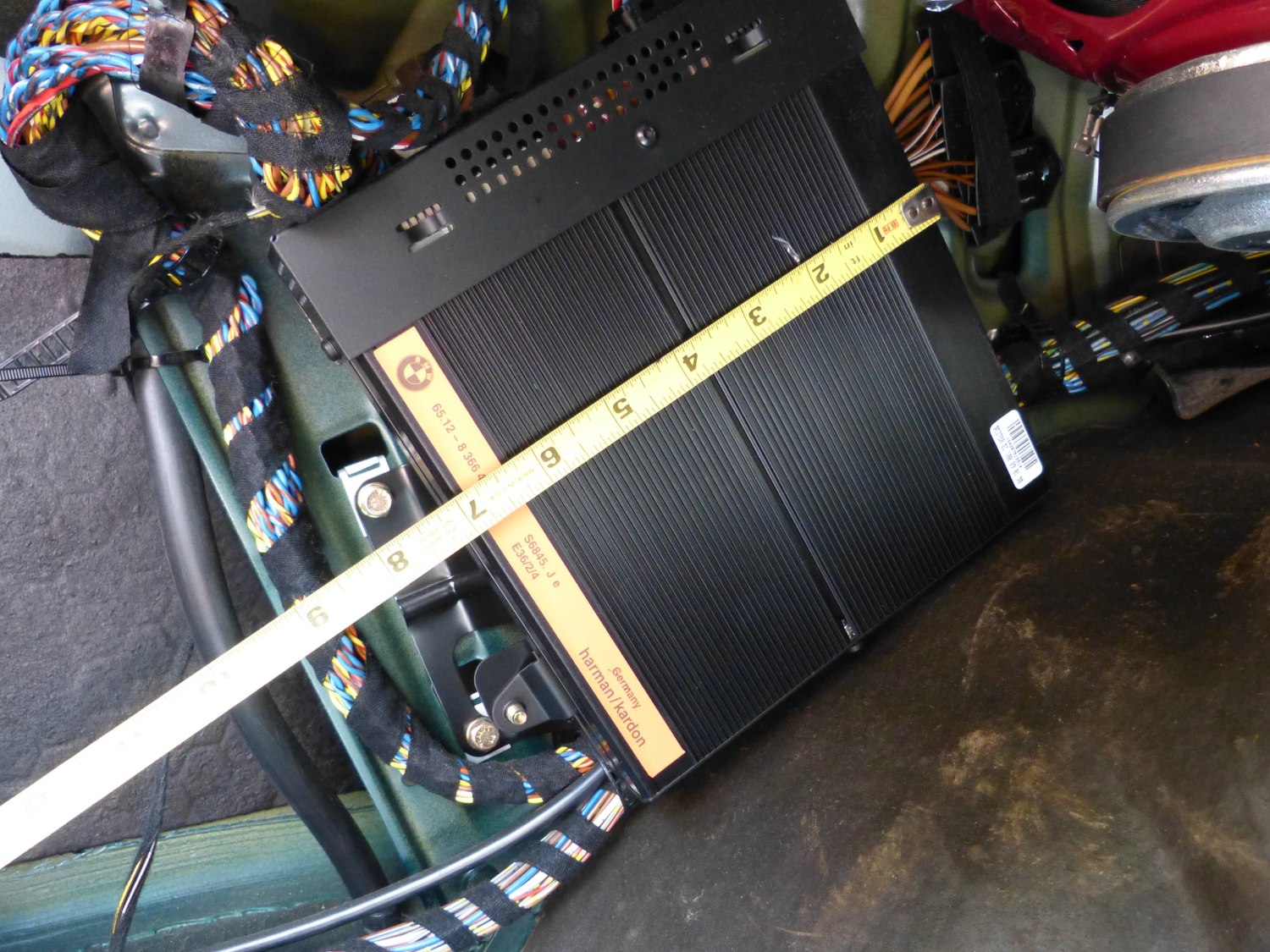
My goal from the beginning was to figure out how to mount the units where the factory amplifier is located. When I removed the trunk liner to better quantify the space constraints I found the following:
- the factory amp is 8x7x1.5” and is offset from the metal structure of the vehicle by roughly an inch.
- about 1/2” clearance exists between the face of the amp and the trunk liner, no doubt for cooling purposes.
- A crease molded into the trunk liner just aft of the amplifier limits the width of the box.
- the bottom of the amp rests against the top of the rear wheel well. This means no connectors may exit the bottom of the enclosure.
- the amp appears to be about two inches away from the left rear speaker and that space allows removal and insertion of the trunk liner without the need to remove the speaker. This means no connectors may exit the forward facing side of the enclosure.
Watch a short video I took with the liner removed.
This translated into a maximum possible volume of around 9x8x2” – far smaller than I would need to mount the MiniDSPs and IsoMax units in their factory cases – to say nothing of the MiniDCs for which there was no commercially-produced case. I reluctantly concluded I'd need to discard the factory cases and repackage all the boards, preferably in a single enclosure. Some searching revealed a 9x7x2 aluminum case made by Hammond Manufacturing so I ordered one from their distributor (Mouser).
 Width of the factory amplifier is seven inches. I have the most flexibility in this direction but that too is constrained by something you can't see -- the trunk liner. |
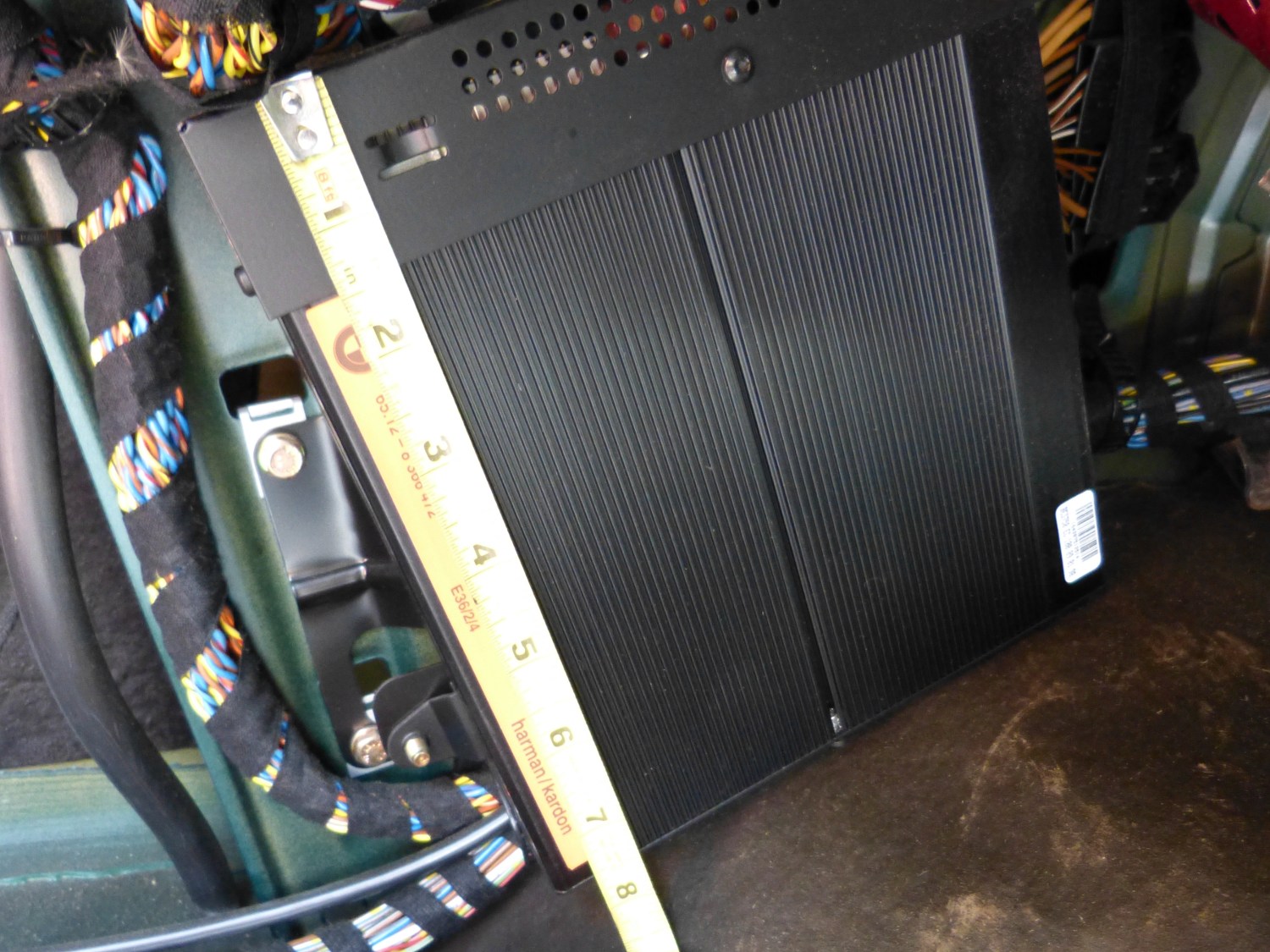 Length is eight inches. The enclosure almost touches the wheel well so no connectors can exit there, obviously. |
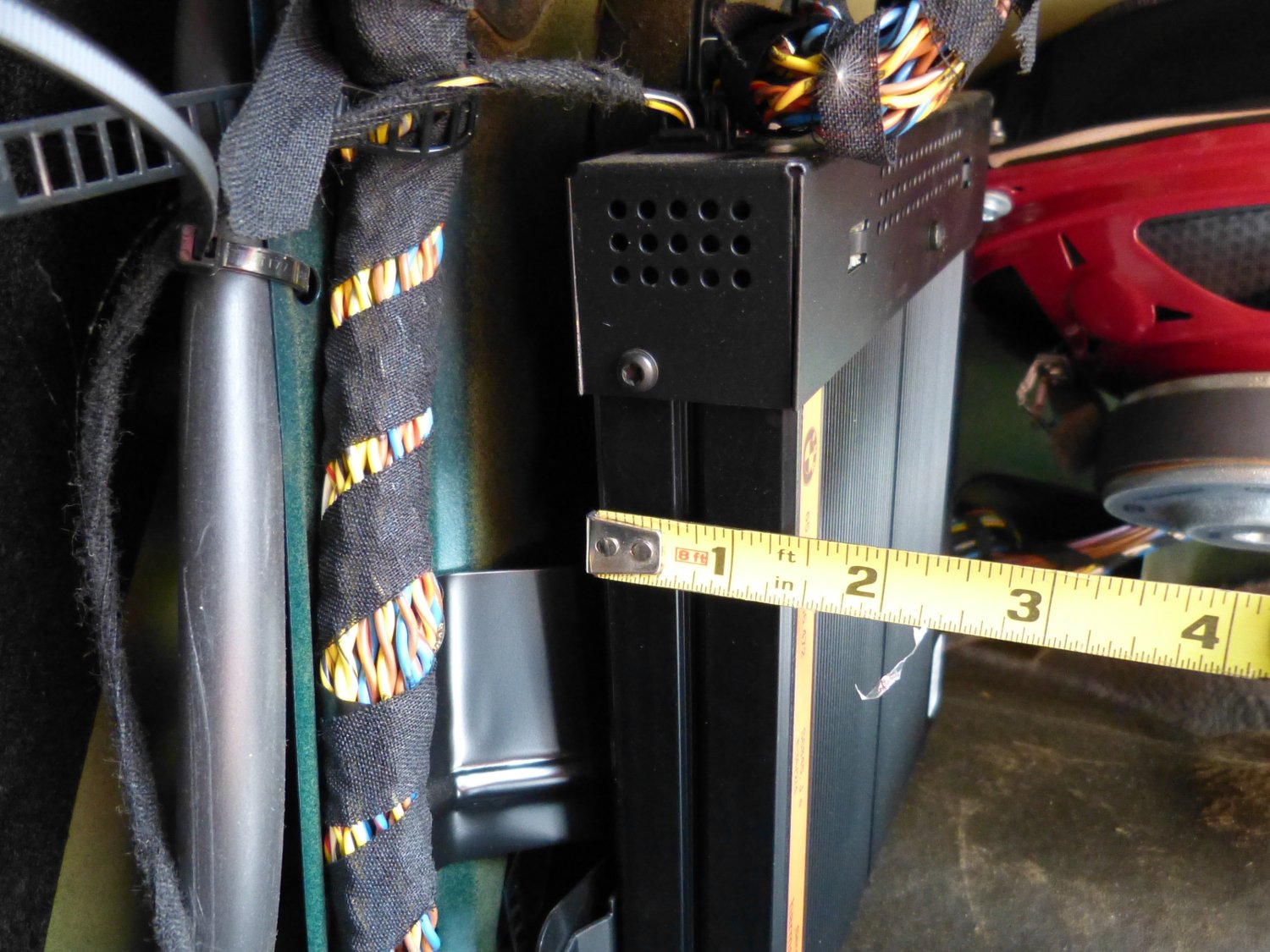 The amp is almost 1.5" deep but is offset on a stamped metal bracket. I hope to reuse the bracket but may have to fabricate my own to reclaim some of that gap. |
I had a particularly difficult time discarding the IsoMax cases since they are works of art in their own right and made of heavy (roughly 18 gauge) steel. However, after figuring out how to use a small screwdriver to unlock the XLR connector shells I removed the boards from the cases and then desoldered the XLR connectors to reduce bulk. The configuration DIP switches were originally mounted to the bottom of the board so I desoldered them and installed new parts on the component side where they would be accessible in the new case.
The greatest space savings came from removing the MiniDSP PCBs from their ludicrously oversized extruded aluminum enclosures that were no doubt sourced off-the-shelf to save cost. Clipping the handles on the unusually tall jumpers reduced the height by a few millimeters but I ultimately decided to remove the euro connectors as well to lower the height requirement by about 4mm and reduce the lateral dimensions of the boards as well. As I will be soldering wires to all of the boards I'll be able to avoid the reputation of these screw terminal connectors to loosen up when subject to vibration.
I considered several quality connectors to interface the enclosure with the harness:
The Molex MX150L is clearly marketed as a sealed connector for the automotive market and so it has a reasonable price (for Molex, anyway) but the pin pitch is 6mm (!) so the connectors in the required pin counts were relatively huge – nearly 90mm between flange mounting holes for the 16 pin models. The connectors had the advantage of being relatively shallow inside of the mounting flange which meant they wouldn't take up precious interior space, and because they were rectangular I knew I could skew them to the top or bottom of the enclosure to reduce any possible interference with the PCBs. But at the end of the day I realized I simply could not fit the connectors on the enclosure in the available space so they were out of the running.
The Amphenol/Sine RT360 series of circular bayonet connectors are works of art mostly designed for high integrity connections in the aerospace market and are made of metal with plastic inserts. As a consequence they are considerably more expensive than the Molex, but despite being somewhat deeper internally (19mm) and circular in nature they have the distinct advantage of being considerably smaller overall. And unlike the Molex the panel mount side of the RT360 connector is also available in both pin (male) and socket (female) configurations. This is important primarily for safety reasons; any connector with live voltage on it should terminate in sockets so as to avoid a potential shorting or shock hazard when the connectors are disengaged. Using differing sexes for inputs and outputs would also have the effect of “keying” the connectors so they could not be installed improperly.
The downside to the RT360 turned out to be cost: nearly $200 for the set I required, and that's not the half of it. These use a very high quality gold plated machined contact which costs around $0.50 in single quantity and they require the use of a $350 indent crimper. I briefly considered $50 “equivalent” Chinese tools but reports indicated they don't crimp consistently well because they are not adjustable like the expensive model. What else is new?
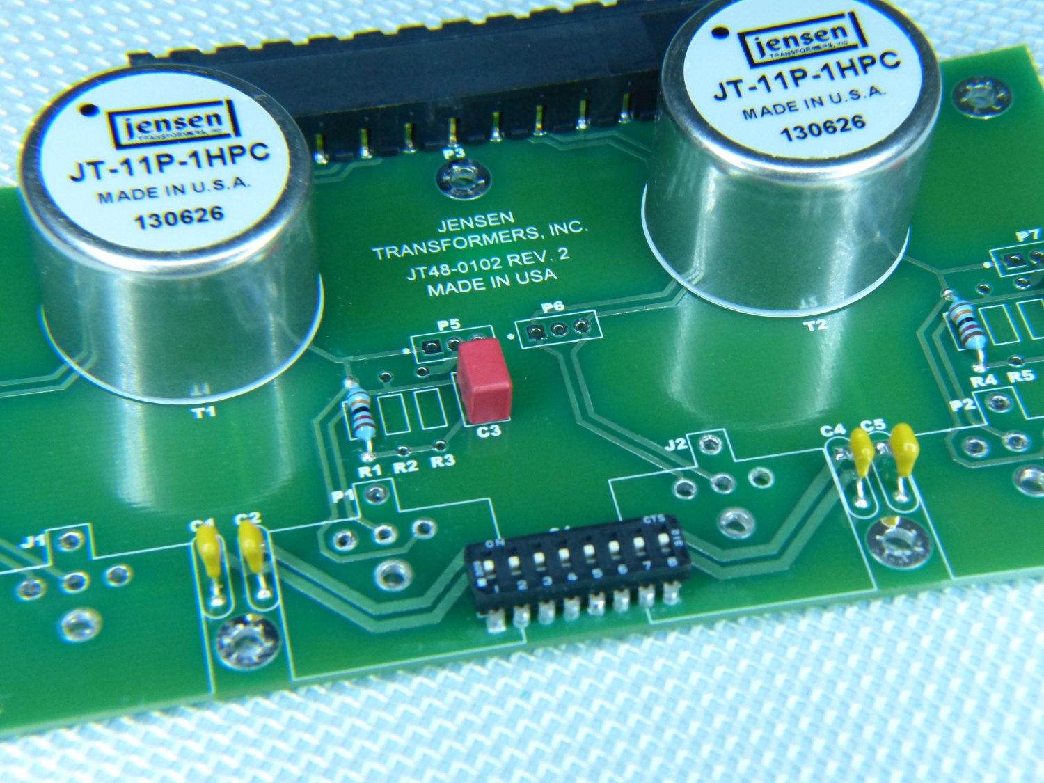 Taken through my LED magnifier for clarity, this shows the IsoMax PCBs with the XLR connectors removed (note the silkscreen outlines) and new DIP switches mounted on the component side. |
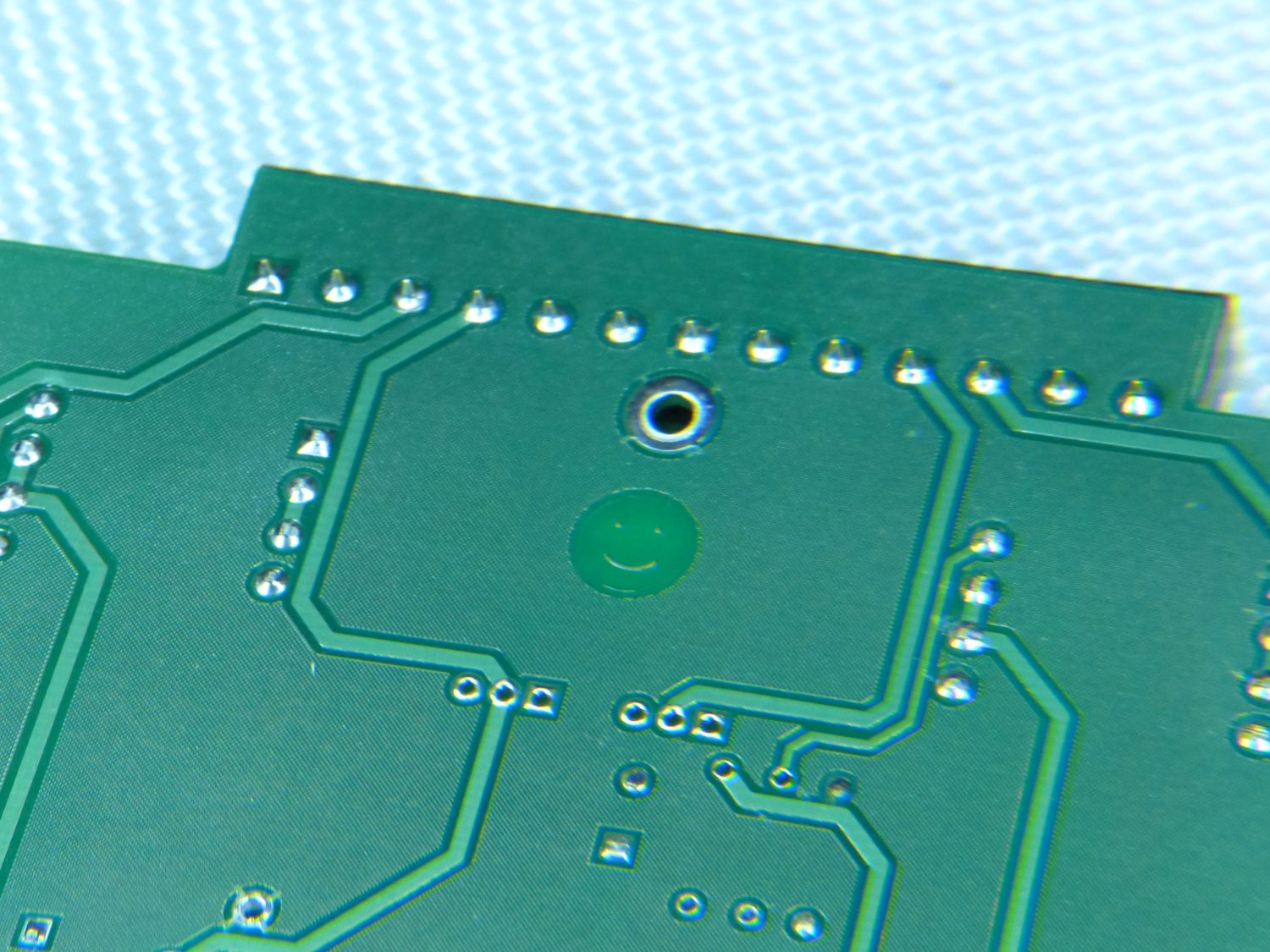 Turning the IsoMax PCB over I was greeted with an easter egg of sorts -- something few end users would ever see unless they were crazy enough to cannibalize the device -- a smiley face. |
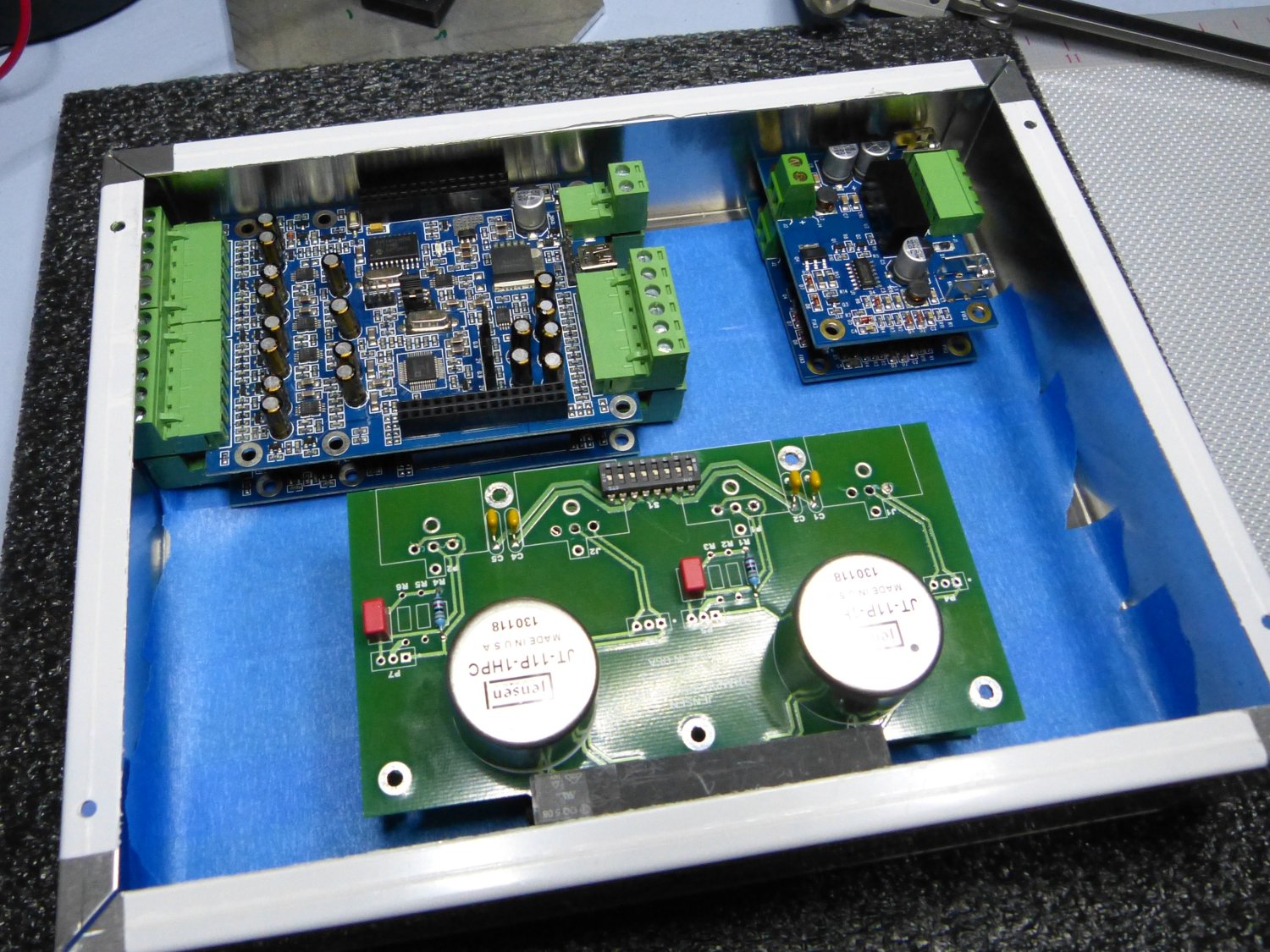
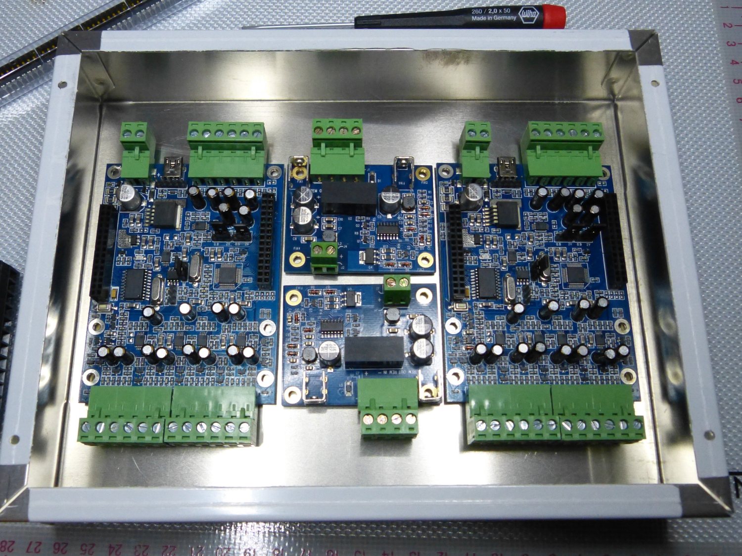 First try -- all the digital stuff mounted on the base of the enclosure. Despite many permutations that followed this orientation came closest to the final solution. |
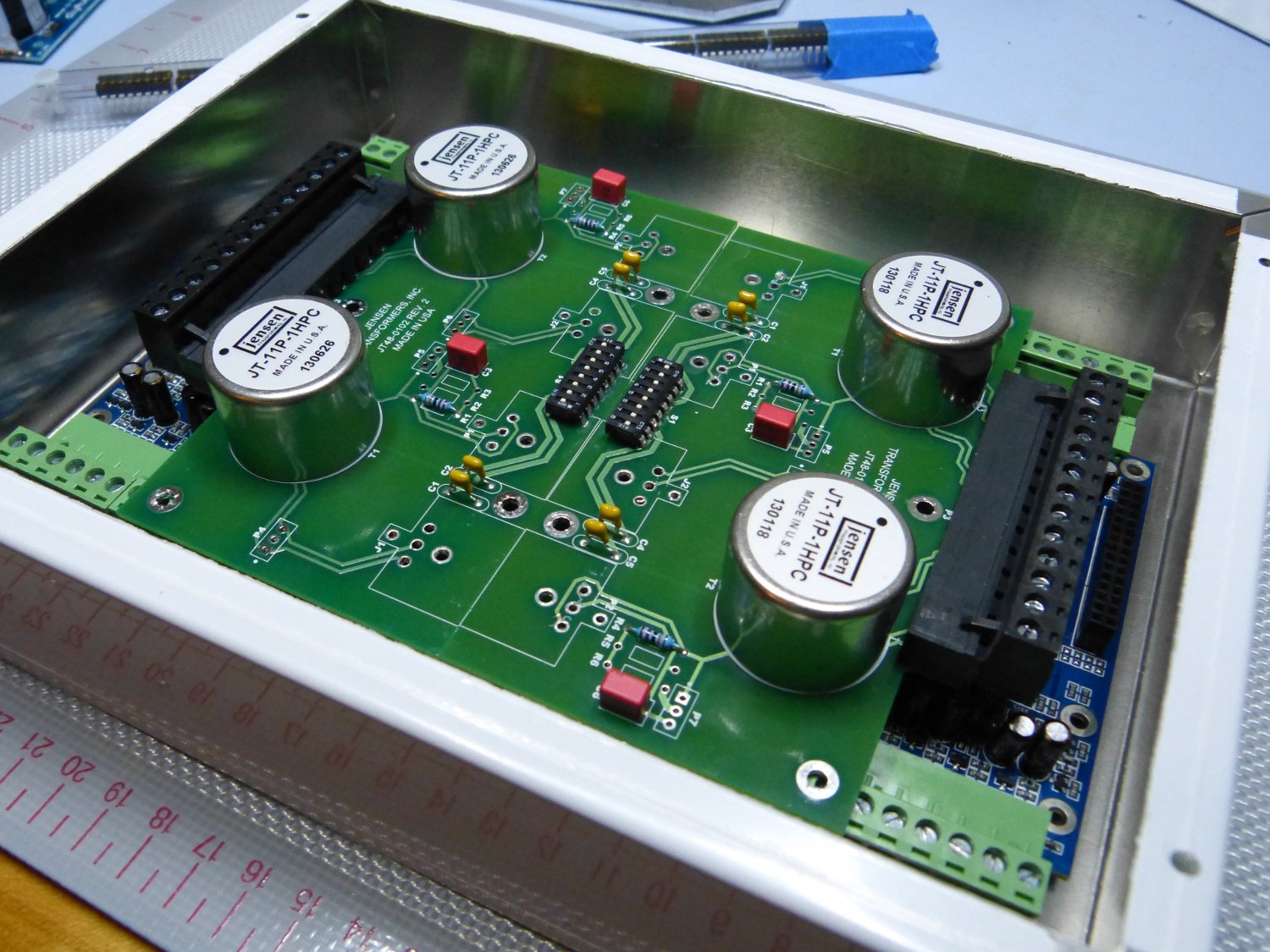 This is an extension of the first orientation with the IsoMax boards placed back to back on top of the DSPs. What's missing here, obviously, is a metal shelf or mezzanine. |
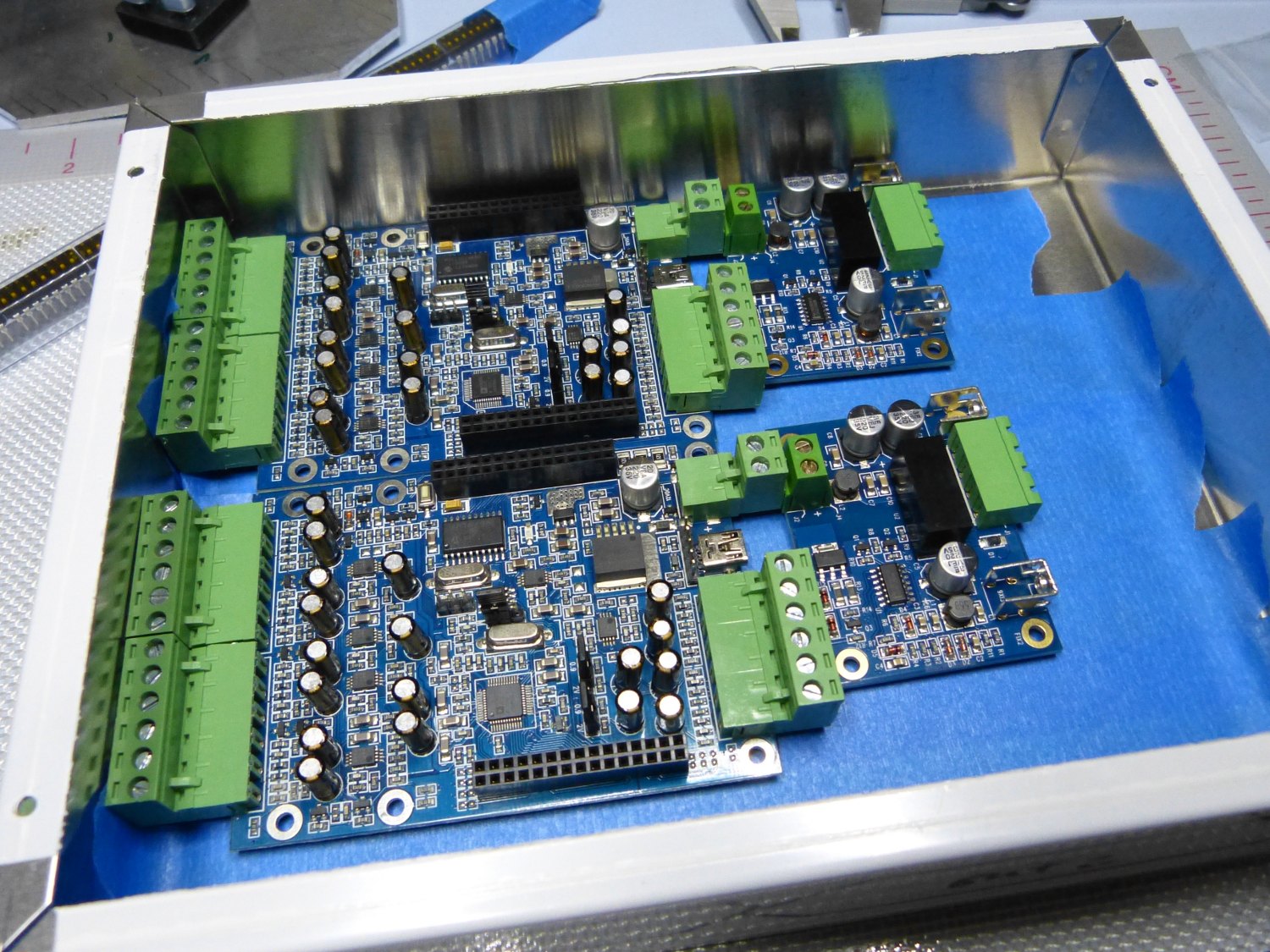 One of the "horizontal" permutations promised to minimize wiring between the DSPs and their power supplies but this didn't make the cut this because it brought the analog input wires too close to the noisy power supplies. |
 Although this orientation would have simplified board mounting this was a dud as well. It looks quite nice until you try to wire it, mount connectors anywhere, and shield the components at the same time. |
This was the proverbial straw so I decided to go “old school” and use d-sub connectors. Two distinct advantages of d-sub connectors are cost and basically little rear depth. The versions that support crimp-based contacts are notably more expensive so I went with solder cups. This naturally eliminated the need for any crimping tools as well. The downside to d-sub connectors is that removing and replacing the cables is a bit more tedious than either the molex or amp connectors, but I had to ask myself a simple question – exactly how many times would I have to remove those connectors even during the initial installation and troubleshooting process? Not often enough to consider the issue relevant.
Then the real head-scratching began. I spent more time at the bench than I'm willing to admit figuring out how to mount the cards in the new enclosure. It seemed like such a simple thing at first, but considering the conflicting requirements related to serviceability (I will need ready access to the DSPs to reprogram them, and to a lesser extent access to the IsoMax DIP switches to troubleshoot grounding issues), signal integrity (unshielded digital and analog circuits in close proximity rarely place nice together) and basic mechanical design (what harness connectors to use, how to simplify the inevitable point-to-point wiring between the cards and connectors, etc.) the task turned out to be far more complex. In fact, after trying at least 10 permutations I didn't come up with the final solution until the USB panel mount extension cables arrived and I attempted to integrate them. The length and minimum bend radius of the cables as well as the size and required locations of the panel mount connectors largely dictated the placement of the PCBs. You'll see what I mean when I display the finished piece.
When it came time to ensure the digital and analog circuitry played nice together I considered the EMC engineer's mantra – it's generally better to prevent transmission of unwanted signals at the source rather than try to shield everything else from receiving those signals, but of course there are cases where it makes sense to shield the receiving unit as well. After all, I don't control all the noise emitters in this car or, for that matter, the surrounding world (think radio transmitters). I decided to use some 18 gauge steel plate to serve as the “mezzanine” that would separate the DSPs from the IsoMax units and model a simple box in Solidworks to cover the IsoMax. I'm not sure if I'll need the box yet but the design will allow me to quickly add it if necessary, even well after the installation is done. Incidentally, if you're wondering why I would use steel vs aluminum it comes down to the fact that ferrous metals shield magnetic as well as electric fields, while non-ferrous metals interrupt electric fields only. Since transformers produce a magnetic field by design and are more susceptable to magnetic fields in general, steel is always the better choice where transformers are involved.
I've assembled almost all of the necessary materials needed to fabricate and finish the enclosure. After that's done I have to build and test the harnesses so I can install them in the car when the carpet is removed in a few weeks. More soon.