


Thursday, August 7, 2014
DSP Enclosure Integration Begins
In the weeks since the arrival of the DSP enclosures I made good progress integrating the components but experienced my share of setbacks. Such is life I suppose.
The first problem was a failed attempt to finish the parts at home. The primer turned out okay but the top coat seemed to take almost a week to dry (the instructions say it's ready in a few hours) and the paint has already lifted in a few locations. This honestly surprised me, since rattle can paint has traditionally been quite resilient (and fast drying), particularly when applied to a properly prepared surface, but that no longer seems to be the case. We can probably thank the eco-nazis for this, as even automotive paints are garbage these days, or so my painters tell me. So these parts will ultimately be sent out for stripping and professional finishing before all is said and done.
When I finally got around to pulling the amplifier and its bracket off the car to fit the spare bracket and the new enclosure -- something I admittedly should have done first -- I discovered the body structure wound up conflicting with the box and access to the USB ports. I sampled other possible orientations but none were satisfactory. That forced me to pick the only other suitable location I could find -- centered on the rear deck between the amps. This is not as terrible as it sounds because it will leave space for a smaller enclosure in which I expect to connect the amplifier outputs to the vehicle's existing speaker harnesses, make it easier to access, and reduce the length of the amplifier signal harnesses considerably -- always a good thing.
 My kingdom for a paint booth. Despite the less than ideal painting environment the primer seemed to come out fine. |
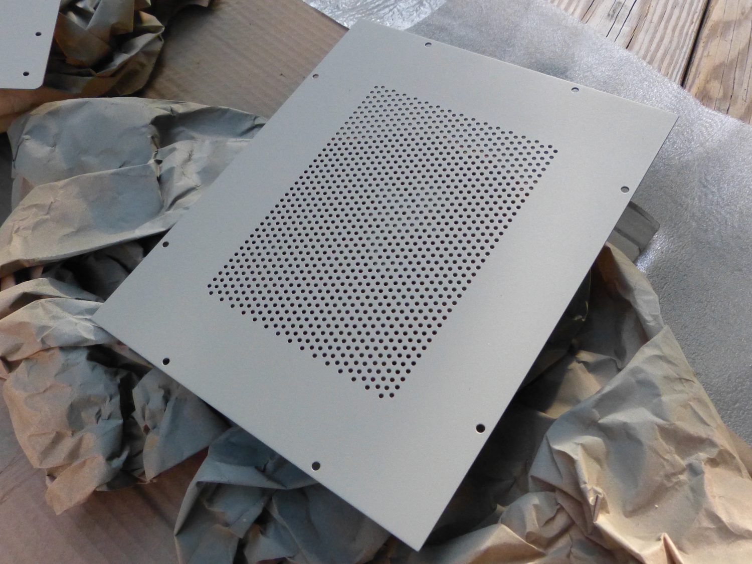 A closeup of the top with a coat of primer applied. I kind of like this matte finish and if it didn't scuff so easily I'd consider it an acceptable finish. |
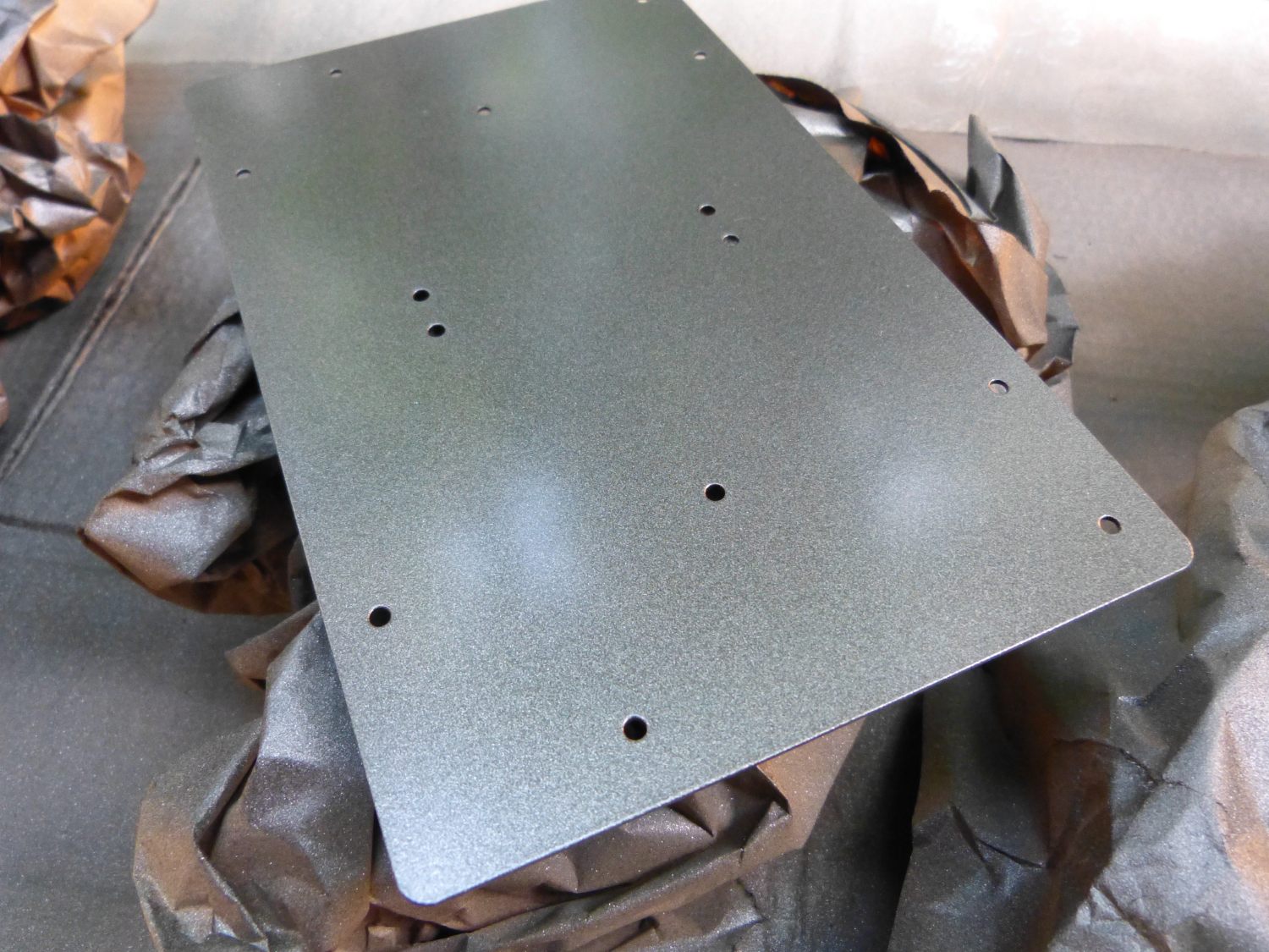 The mezzanine with "midnight black" metallic rattle can finish applied. There's a bit too much flake in this paint for my taste. |
Due to the irregular surface of the rear deck and the need to be able to remove the enclosure for future debugging I realized I would have to construct a custom bracket for it that would reach nearby structure sufficiently flat to accept the threaded inserts I planned to install. I built a prototype bracket in Solidworks using the enclosure model as a dimensional reference and then printed out a 100% copy of the bracket and used that to trace the outline on some 18 gauge steel I had handy. To make a long story short, the bracket had to be produced in two pieces and I have decided to use them as a template to determine the various bend angles required and then send a one-piece bracket out to be manufactured from some heavier gauge steel (probably 14 gauge).
While I did manage to test fit and assemble all the boards and most of the wiring in the enclosure, a last minute bench test revealed a strange issue with the remote inputs on the MiniDCs. When I tied the two remote inputs together and connected them to the same 12V source my power supply went into current limiting. I had preset it for 650ma, more than enough for the job, and as yet have not figured out why this is happening. The cards don't appear to be damaged, and in fact the LED status indicators on both MiniDSPs flash with the supply voltage pulled as low as 6V in this state, but as I won't have that protection in the car I can't install the boards in this configuration or I'll let out the magic smoke. That won't do.
I sent email to the MiniDSP guys but they have so far been less than helpful. They first of all suggested that I could "easily" power two MiniDSPs from a single MiniDC and eliminate the issue altogether. I didn't consider that acceptable because I know for a fact that the MiniDC supply module is rated at 3W and two MiniDSPs pull more than that (at least on my bench). They added that "everyone does this", but here's the problem -- not everyone is installing these units in a car that will be heat soaked to 120+ degrees in the summer.
They then asked for a drawing of my wiring configuration. I did that and the response was baffling to the say the least; they suggested that the wire size I was using might have caused an overcurrent condition. I'm sure any EE would would agree this is laughable. I volunteered that this might be related to oscillation of some components on the board (something I've seen in amplifier design) but without a BOM (bill of materials) or a schematic I was shooting in the dark. I asked them to send the schematics to me twice. Response: crickets. I have since come to the conclusion that using an optocoupler to isolate the signals involved may fix the problem as well as provide some potentially helpful galvanic isolation of this signal. I have some parts on the way and will be breadboarding those up shortly. We'll see what happens.
This testing also revealed that each MiniDC draws nearly 40ma in its idle state (with the remote signal low and MiniDSP disabled). This is no big deal if the engine is running but I'll need to find these units a switched power source. I'm not sure the harness near the factory amplifier provides such a thing. I may need to run a power cable back from the headunit for this. It's time to dig out the E36's wiring diagrams.
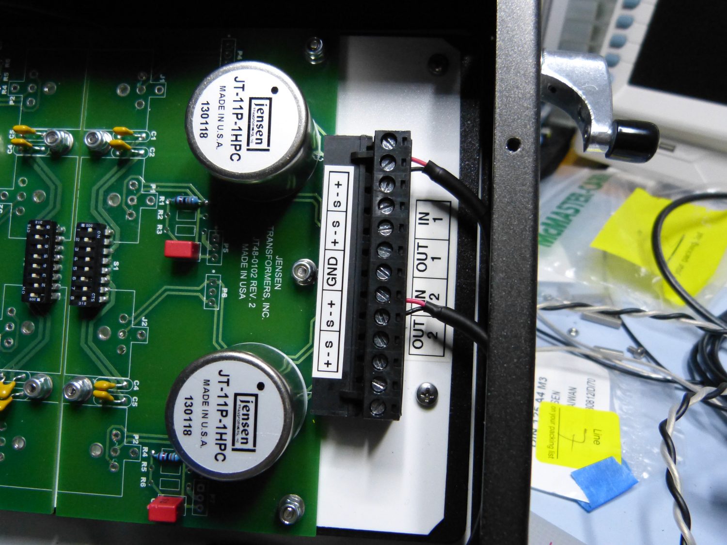
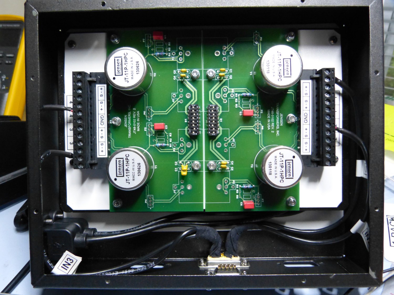 The input connector is shown here wired to the euro connectors on the IsoMax boards. Fabric (friction) tape helps to isolate and organize the wiring. The white layer is a plastic insulating layer. |
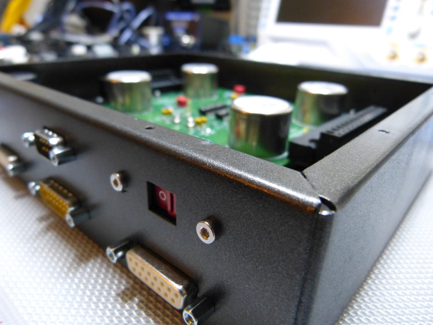 I test fit all of the connectors and everything fit together perfectly, which was no surprise given that I dimensioned the holes to accommodate the primer/paint thickness. |
 I applied some P-Touch labels to the IsoMax connectors to make wiring easier. I also applied some heatshrink to dress up the ends of the cables. |
On the upside I'm happy with how the box is coming together. In the pictures you can see the enclosure I finished with a top coat. The connectors were temporarily installed in the front panel to check fit. I used 0.4mm in Solidworks as an allowance for paint and that provided ample clearance. I could probably reduce that to 0.2mm on the next project. A good datapoint.
You may notice the white layer under both the IsoMax boards and on the floor of the enclosure. That's an insulating layer that prevents the solder side of the PCBs from shorting against the enclosure. Electronics supply stores charge big bucks for rolls of "approved" insulating sheet material that is often used in power supplies but I found a good source of functionally equivalent material on Amazon in the form of roughly 1mm thick flexible cutting boards. I think I paid $7 for a pack of five...and I did need a flexible cutting board in the kitchen, so this was a win-win.
The IsoMax boards are semi-permanently attached to the mezzanine using M3x10mm low-profile socket cap head screws, identical to the ones holding the red recessed switch to the front panel, by the way. The screws are inserted through unthreaded holes in the mezzanine and secured to it using a washer and hex nut on the top side. This produces a stud with a roughly 2.5mm standoff height onto which the PCBs are mounted. I've topped them off with M3 nylon locking nuts to ensure that they will not vibrate loose. I am planning to use the same mounting system on the MiniDC/MiniDSP boards as well.
I had originally applied heatshrink to dress up a lot of the wiring terminations in the enclosure but was forced to remove much of it when I realized that it noticeably reduced flexibility of the wires where I needed it most. I looked into my past for a solution and found it: the same 3M "friction tape" I used in the electrical trade. The best thing about this stuff is that it's sticky enough to bond well but easy to remove and control the tension applied. Of course, where space permitted (like on the ends of the input wires leading to the IsoMax euro connectors) I used heat shrink because I think it provides a more polished appearance.
Powdercoating Lessons Learned
Four years ago I pulled the rear end out of the car and powdercoated the subframe. While under the rear end recently I noticed that rust had taken hold again on several areas of the subframe, mostly the bottom portion where I typically jack the car. While conducting research into methods available to professionally finish the DSP enclosures I realized why the powdercoating failed so soon: I neglected a couple of essential steps in the preparation process.
Most people who restore cars typically sandblast and then powdercoat so I figured I'd follow suit. And for a car that sits in the garage or goes out only on sunny days as many restored cars do, that's probably an adequate finishing technique. However, what I didn't realize is that metal preparation is far more critical on a car that serves as a daily driver and is routinely exposed to the corrosive effects of salt spray for a good four months out of the year.
It turns out that powdercoating raw metal provides the weakest protection against corrosion and in industry standard salt spray tests typically protects the metal substrate only 25% as long as parts that are prepared properly with a conversion coating and a quality catalyzed primer. The most popular conversion coating is zinc phosphate, applied in either spray form or ideally by immersion. The conversion coating is NOT a primer but rather a means to inert the surface of the metal such that it becomes less chemically reactive. A quality catalyzed (or epoxy) primer serves to protect the conversion coating and provide a further barrier between the metal and a failed top coat.
If I had to it all over again I would have performed these extra steps even if it meant sending the components several states away to a proper finisher. If you're contemplating doing the same degree of work on your car and expect to continue driving the vehicle in the real world I cannot emphasize enough that you need to take corrosion protection seriously and pay to have the parts prepared and finished professionally or you'll wind up doing the work over again as I may wind up doing in the next couple of years. Rattle cans? Don't make me laugh.
Paint Prep and Parts
After wrestling with the decision for some time I finally decided to buy new OE non-M front and rear bumper covers and rocker covers. While several people encouraged me to go for the M Technic parts when I ran the numbers I quickly realized that they would have added a lot more cost to this little adventure (even at my discount level) for little real world benefit. Plus, I reasoned, my goal all along has been to keep the car as close to stock as possible, and while I have put M parts on the car I have carefully selected those parts when I knew there would be a less obvious external change or a potential increase in performance. That was hardly the case here.
I did, however, invest in all new exterior moldings, including the M "wide" trim. My parts guy was able to source the wide door trim with the "badge delete" option, so this car will remain a "sleeper" with all of its M bits installed. No poseur badges for me. I did ask for the opinion of a few people who appreciate the history of these cars about equipping it with euro clear lenses and all said "no way...keep the turn signals stock yellow" so I picked up new yellow corners and side markers as the foam on my original 16 year old parts had noticeably disintegrated. Those will be combined with ZKW halogen projectors and new fog lamps to round out the new front end illumination package. This winter's evening drives should be a hoot -- I'll actually be able to see more than 30 feet in front of me!
While discussing my paint plans with my brother he suggested that I avoid painting the door jams if it meant removing the VIN and other coded stickers as proper restorations usually place value on having the original stickers and no clear build up around labels that have been obviously masked. A call to my parts guy revealed that BMW does, in fact, provide replacement stickers. The VIN sticker requires the dealer to fill out some annoying forms and ask some stupid questions including the "reason for replacement", but at least the stickers are available. I'm not sure if they'll look like the original sticker or the newer ones like on my E46 but I don't really care, so long as the sticker is an OE part and not an aftermarket replacement. The tire pressure label is also coded to the car, and apparently must be specially prepared by BMW so I plan to order that as well. Fortunately both stickers are very inexpensive...as they should be.
This weekend I'm planning to swap my summer tires for my winter wheel set as I care somewhat less if they get any overspray on them. I'm also planning on pulling the door panels (the right side especially so I can use it as a model to cut the new door panel), and pulling the rear seats and the headrests so I can order the leather and get a jump on that work while the car is being painted. The front seats will go out when I pull them to pull the carpet. And so it begins...
Mileage: 252100