


Sunday, July 30, 2017
Cylinder Head Removed
I began today by pulling the oil filter housing. I had to remove the oil filter cover to access the cam sensor that remained in the head but I neglected to reinstall the cover before I removed the housing so when I turned the unit upside down to inspect the filter housing gasket a bit of oil drained out on the floor....and onto my shoe.
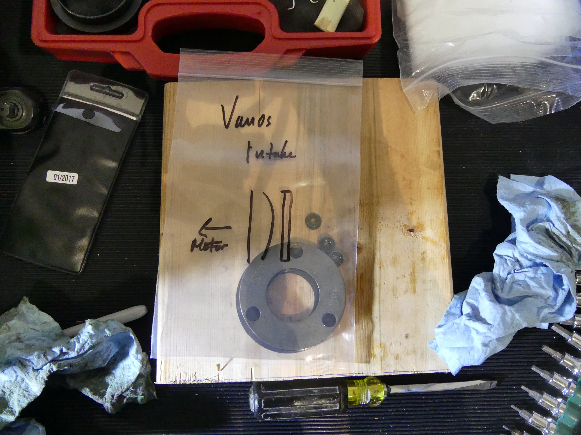 It's one thing to remember how things go together. It's quite another to remember how things go together a month after you took them apart. I've been sealing all the parts in bags labeled with as much detail as possible. In this case, the installation order of the intake cam stop disks and diaphragm spring. |
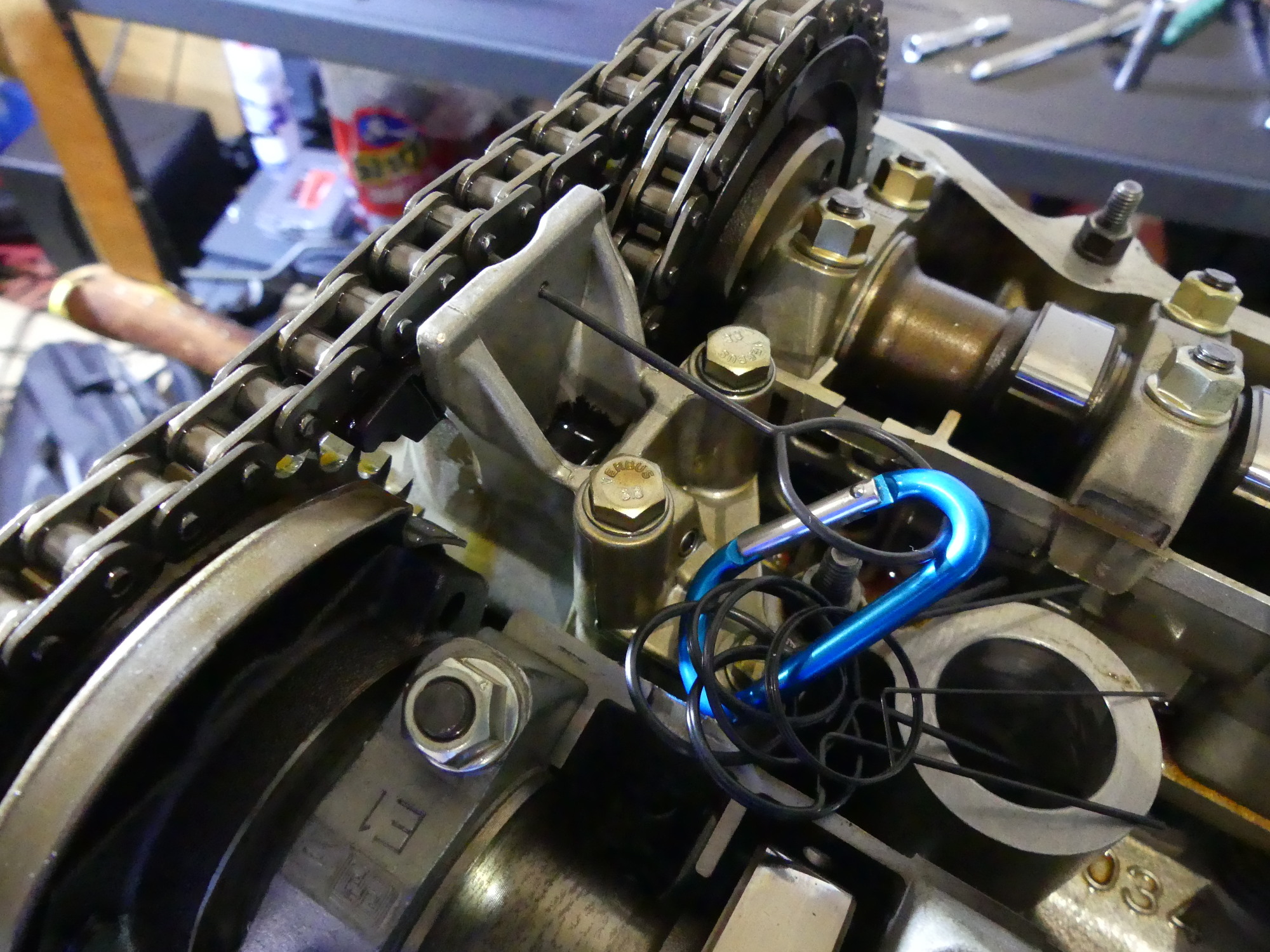 One of the first steps in disassembling the head it to use a pin to lock the secondary timing chain tensioner in the fully compressed position. Pressing downward on the chain directly above the piston is a good way to sanity check the health of the tensioner. High resistance is good. |
 The VANOS is held to the head with a few nuts. Removing it requires loosening the four torx bolts on the exhaust cam sprocket and then using the special VANOS wrench to rotate the exhaust sprocket (and hence the intake) clockwise while pulling the vanos away from the head. |
After several minutes cleaning up that mess I took a closer look at the housing and found the gasket completely flat where it mates with the block. I replaced the gasket back in 2010 and it clearly has not faired well. It absolutely astounds me that BMW can produce a silicone gasket for the intake manifold that will survive a nuclear blast but they continue to use this shitty rubber material to produce a $5 gasket that costs hundreds of dollars in labor to replace. Out of frustration I just searched for a Viton gasket and, sure enough, Bavarian Autosport now sells one. It apparently became available just last year, which explains why I didn't find it last time. I plan to order the Viton part and return the BMW gasket if I can. It's only $5, but that's better in my pocket than theirs.
I then got to work on the head and removed the vanos. The first thing I can say is that my VANOS is definitely worn. The piston is supposed to slide in and out of course, but mine seemed a bit too eagar in that regard, which may indicate that the seals are in poor shape. I also verified that the shaft has a bit of axial play so my call to purchase the Beisan anti-rattle kit was spot on.
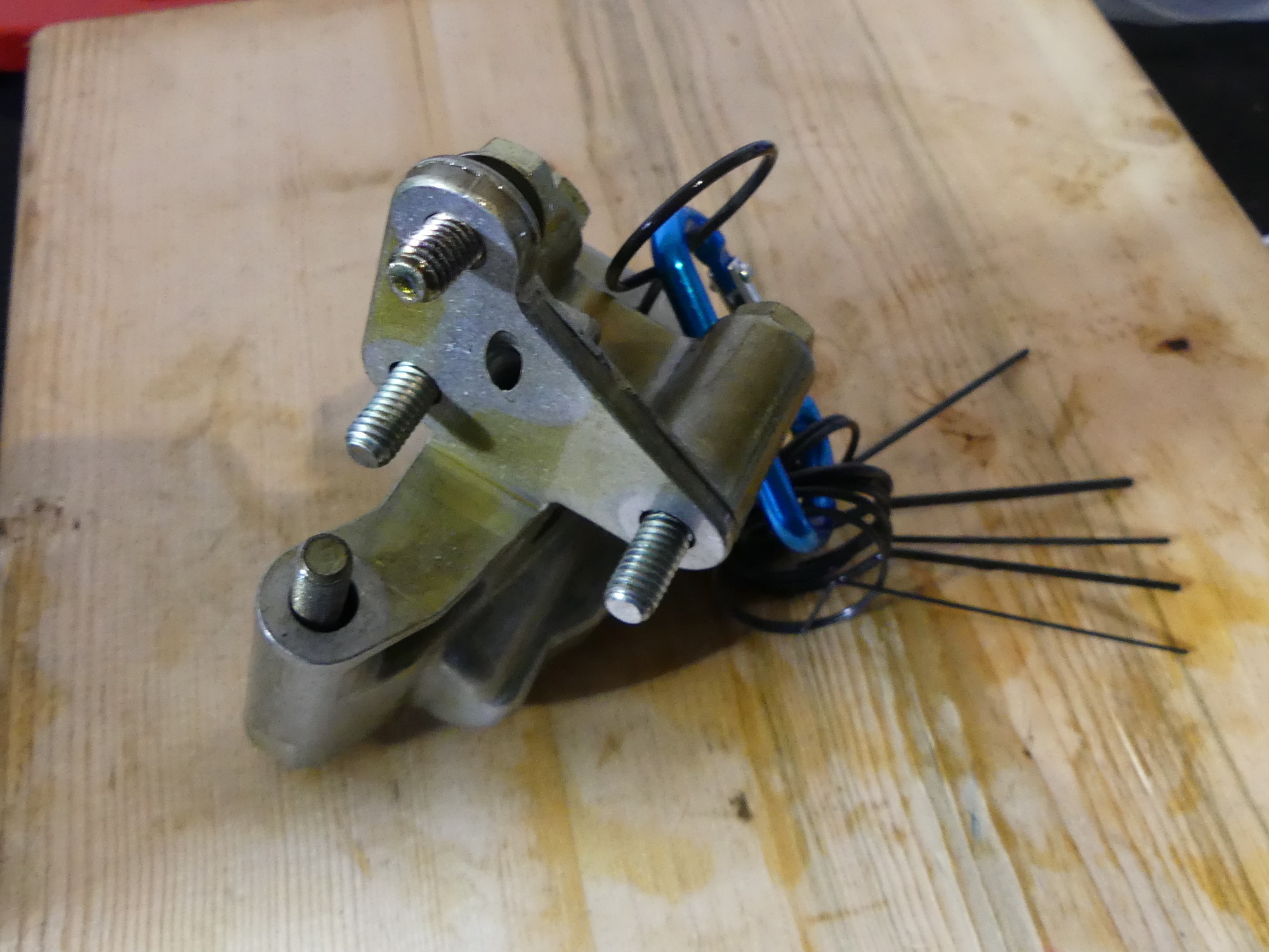 The secondary timing chain tensioner is fastened to the head using four bolts of three different sizes. While it's fairly obvious what goes where, the easiest way to confirm you have the bolts in the right place is to insert them in the tensioner body and verify the exposed threads are all the same length. |
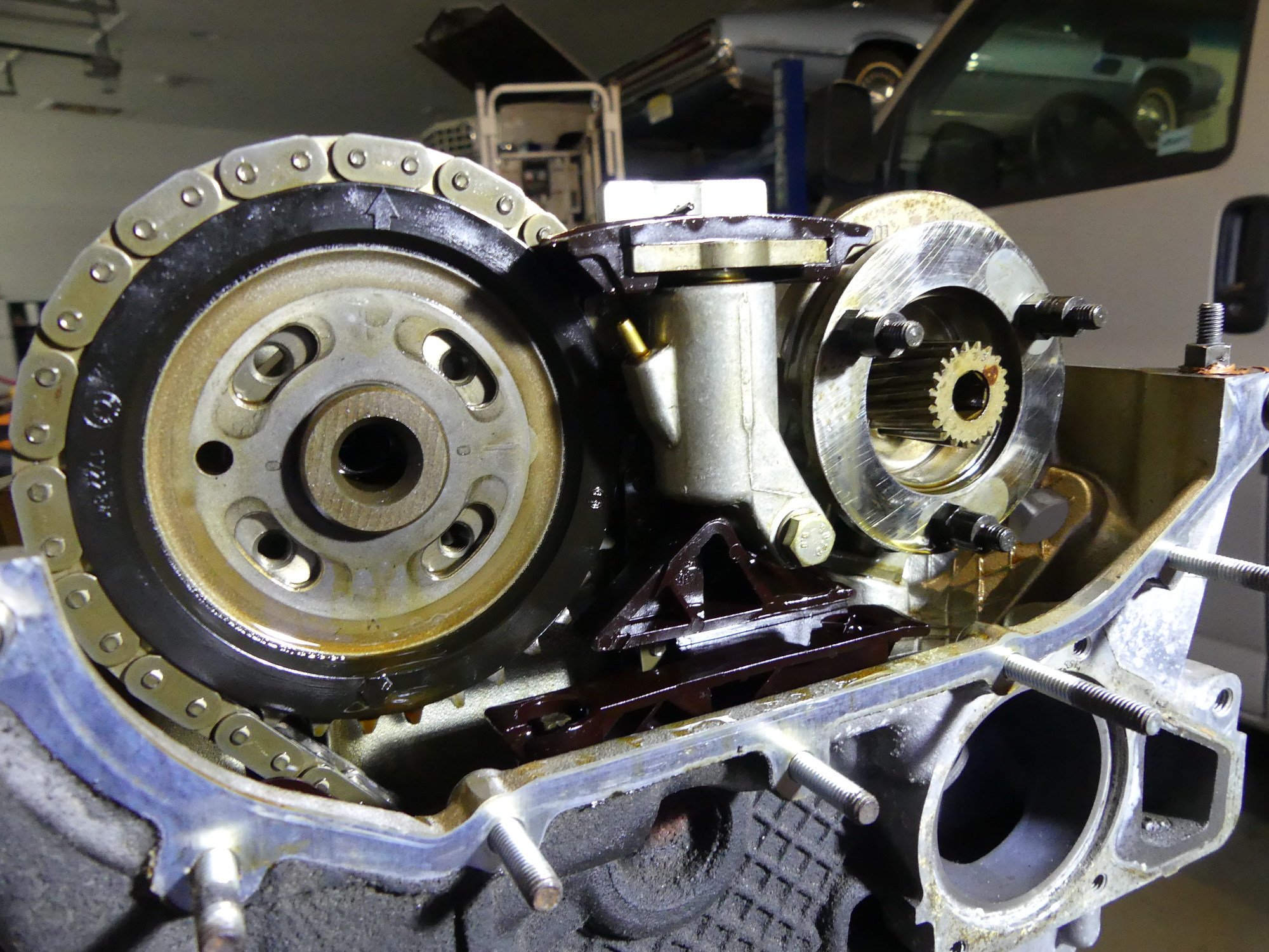
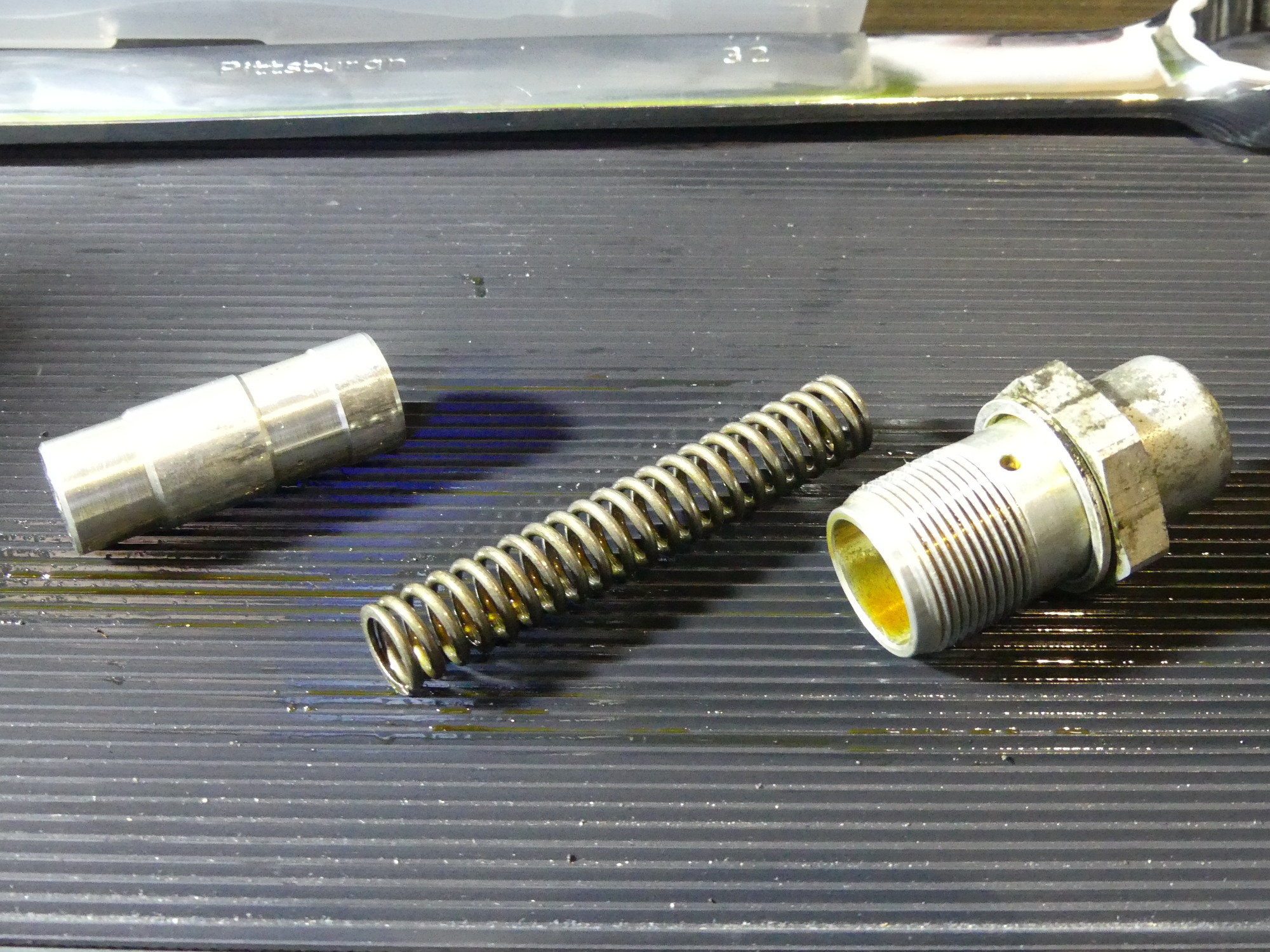 One of the seemingly few original pieces that will go back into this engine is the primary chain tensioner. Even the spring appears to be in good shape -- probably because it's bathed in oil during normal operation. I'll use the piston and body with 8 US pennies to help me time the engine before installing it permanently with the spring. |
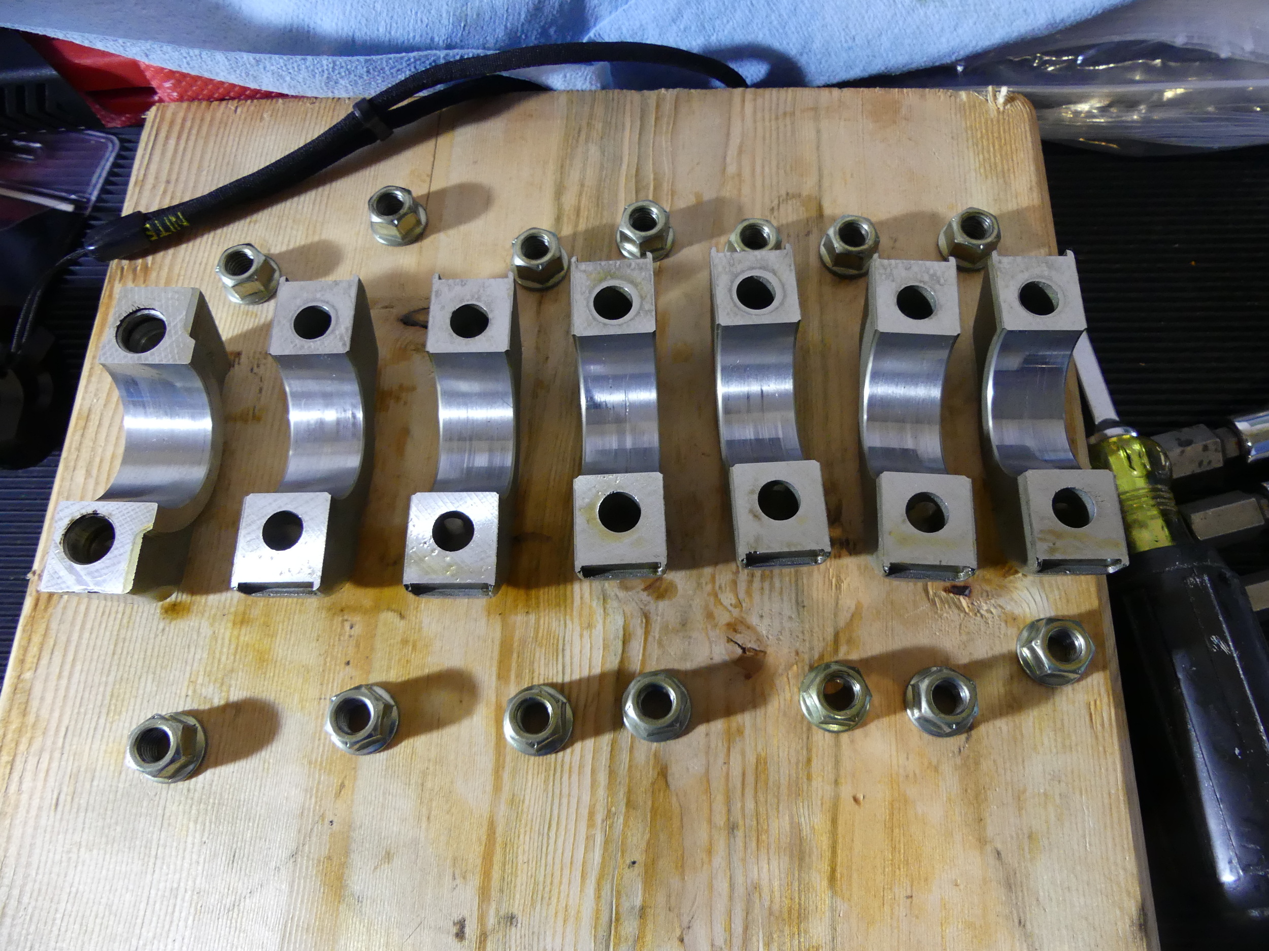 Here's where things get interesting. These are the intake bearing caps. E1 on the left, E7 on the right. The worst is E4, which I fear would not pass the fingernail test. If it doesn't pass I may not have any choice but to buy a new cam tray. And since the cam looks worse -- a new intake cam may be necessary as well. |
Looking at the wear pattern on the 4mm spacer plate in relation to the mounting studs I can tell that they are not centered, but I don't think that is strictly necessary or indicative of a timing error. The issue, of course, is I still don't know the source of the cam position error I found the other day.
I then got to work removing the cams. To make a long story short I'll say that I was successful using what I'll call the 3/5 lobe technique which involves the following procedure:
-
Place the cam lobes for cylinders 3 and 5 at the position where they are both barely touching their respective lifters.
-
Remove all the cap retaining nuts EXCEPT for cylinders 3 and 5. I put a piece of blue tape on the caps for 3 and 5 to ensure I wouldn't accidentally loosen those nuts in this step.
-
Remove the four cap retaining nuts remaining for cylinders 3 and 5 by first cracking each nut loose in a circular pattern, and then loosening each nut 1/4 turn until the cam is no longer pressing on the lifters.
I can confirm that this technique works and is far better than the cylinder 1 technique because the cam does not rotate on its own. As I went through the 1/4 turn series I discovered that my cams were fully off the lifters with plenty of threads to spare so I expect this technique to work for the assembly process as well.
I pulled the cam trays and lifters out just as expected, and found the neodymium bar magnets I selected worked perfectly to retain the lifters. In fact I knew exactly how well they worked because once the assembly was on the bench and I removed the magnets, picking up the cam trays resulted in all of the lifters smoothly falling out of the bores.
 The bar magnets I selected for retaining the lifters worked like a charm. They were easy to install and remove despite their strong magnetic field. Once I removed them on the bench and lifted the cam tray slowly all of the lifters just remained behind on the table, proving that they are quite necessary for this task. |
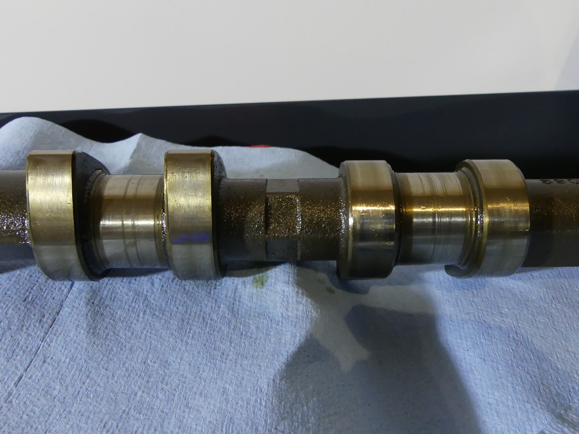 A sample of the bearings on the intake cam. This is the worst of the damage. I was wearing gloves when I removed the cam so I didn't do the fingernail test, but I'm pretty sure this won't pass when I get around to it. Something tells me I'll be buying a new intake cam at least. The exhaust cam doesn't look nearly as bad. |
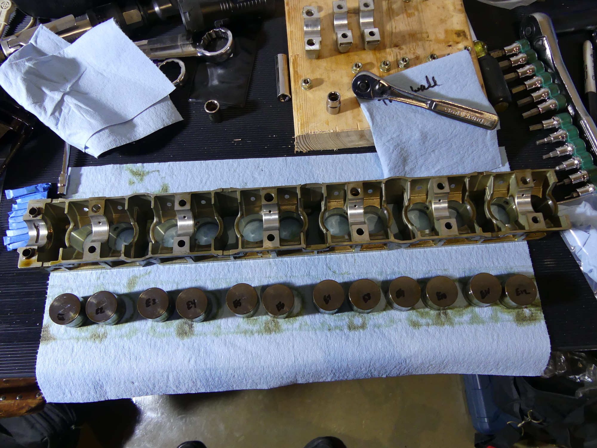 Just a glamour shot of the lifters removed from the cam tray. Despite the fact that I have all new lifters waiting to be installed and I may wind up buying at least one new cam tray I labeled all of the original lifters to aid reassembly if required for some unforeseen reason. |
Finally, I used my special E12 torx socket to remove the head bolts. I did this in the same order recommended for assembly though I don't think that is strictly necessary. I used a dead-blow hammer (not ideal, but all I had -- I really need to buy a rubber mallet for jobs like this) to tap the bottom edges of the head in an effort to break it free of the block but when that proved fruitless I started looking for more screws...and found the two E8 torx at the very front of the head where they bind the head and the timing cover. With those screws removed a couple hits with the hammer broke the seal and the head came off the block easily.
I found the head gasket very well bonded to the block. I used a plastic scraper to get under it but when that proved too flexible I carefully used a screwdriver to lever the gasket material upward enough to grab it and then pulled it off. A lot of material was left behind on the deck of the block. I don't strictly need to remove that but probably will.
Condition Analysis
The timing chains appear to be worn a bit on their faces where the links continually ride on the guide rails, and the face of the secondary timing chain tensioner guide is worn as one might expect. The chains also appear to be in good shape cosmetically but on the whole the joints don't seem to rotate as smoothly as I expected. I haven't pulled the new chains out of their packaging yet but I am eager to compare the new to the old to see if the links on the new chains rotate a bit more freely. If they do then the resistance of the old links is a sign of wear.
A close look at the sprockets shows some wear typical of an engine this age. The teeth are noticeably worn on one side. The set of sprockets is a bit over $100 but I can't see going this far and not replacing them so I'm likely to add those to the next order. The only other wear-related item I see in this system is the diaphragm spring which is sandwiched between the 2mm and 4mm stop disks. Given that it's only a few dollars I'll replace it for good measure.
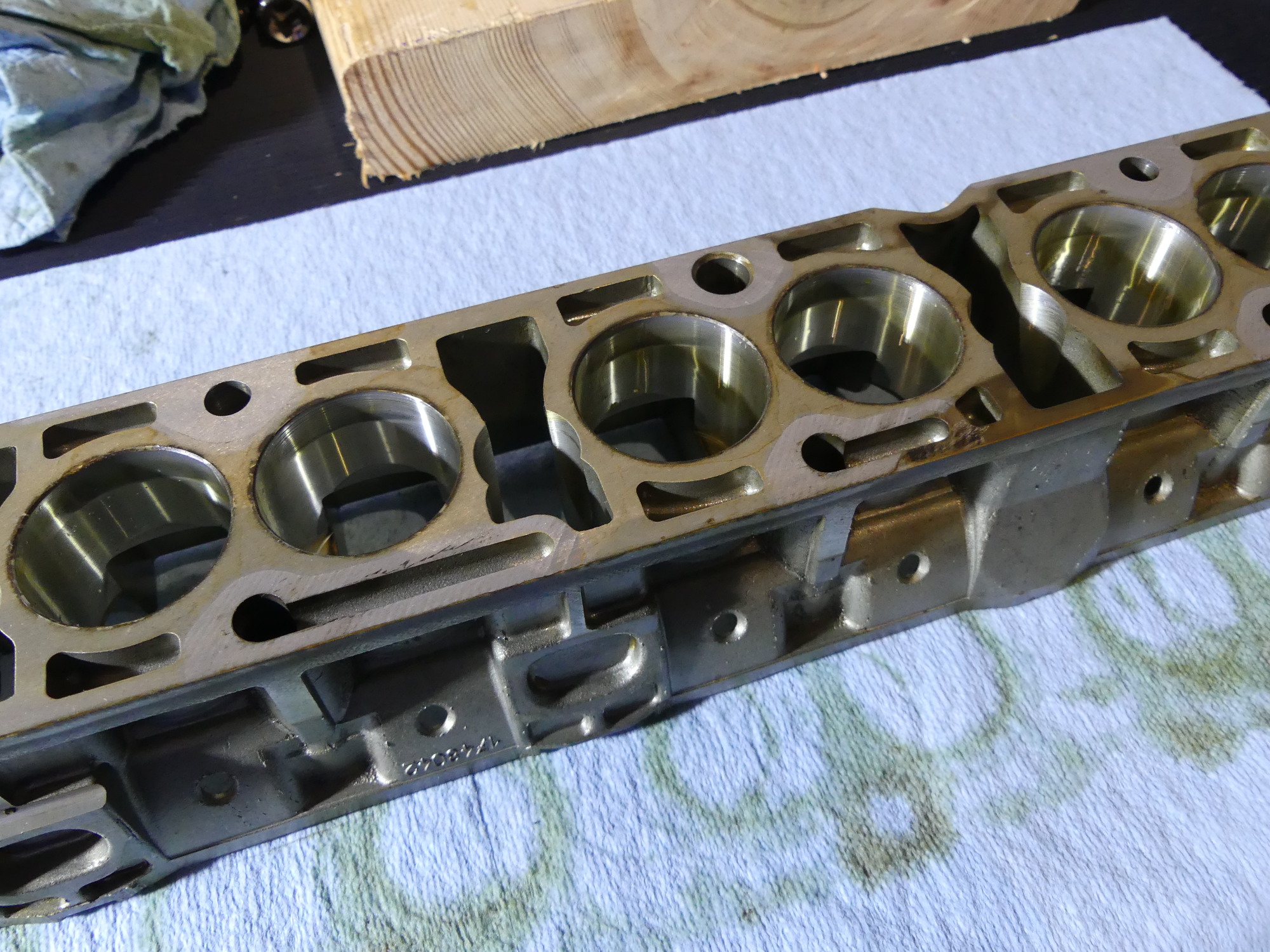 The lifter bores on both cam trays are in remarkably good shape, though a wear pattern is obvious. I only found a few vertical scrapes in a few of the bores and what I found would likely pass the fingernail test. And this is the real shame -- I may have to discard the tray anyway. |
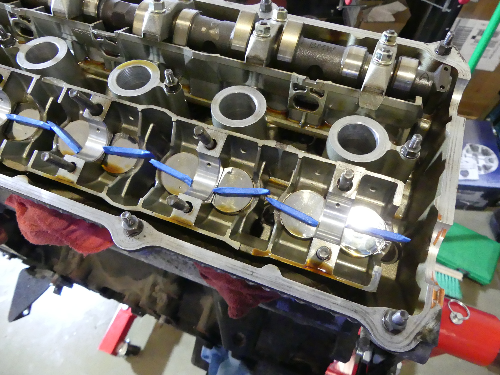
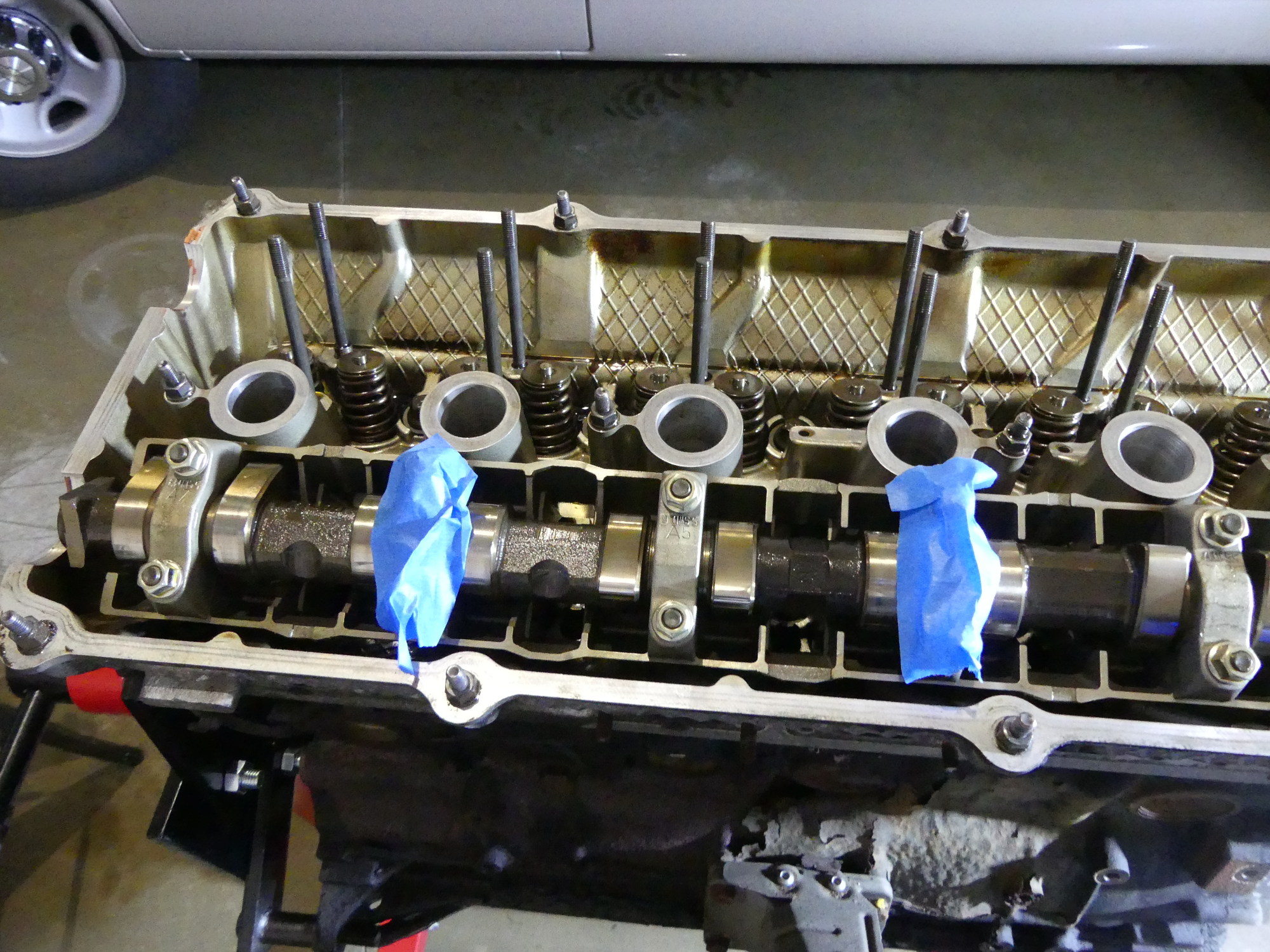 When you're trying to get things done it's easy to get punchy, so I placed some blue tape over the caps that I was NOT to loosen initially to remove the cams. Once all the other caps were removed I removed the tape and then removed the nuts a quarter turn at a time. |
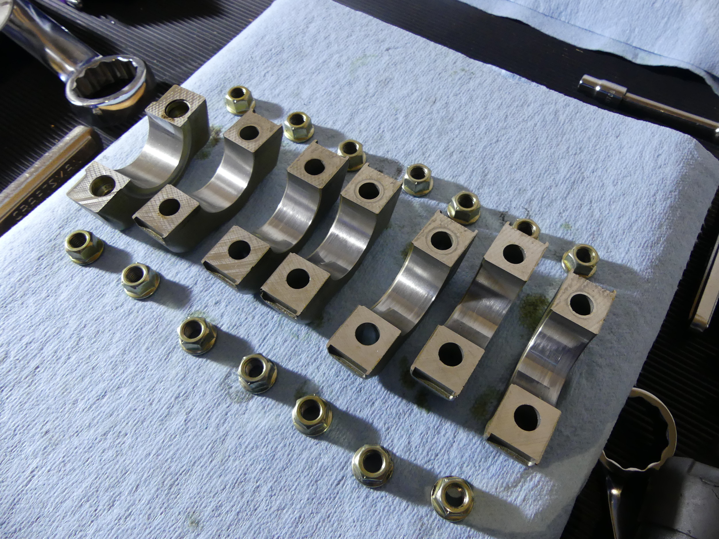 The exhaust bearing caps are in nearly perfect shape aside from a bit of additional wear on caps A6 and A7. These are shinier than the others, which indicates prolonged contact across the face of the cam bearing surface. Good that it's consistent wear across the face of the bearing. Bad in general. |
Overall, the exhaust cam and bearings are in much better shape than the intake cam. I'm not sure why there would be any difference but it may have something to do with how oil circulates in the head. Perhaps the exhaust cam gets oil pressure first during cold starts.
Two or three of the intake cam bearing surfaces are scored slightly and so are the associated cam bearing caps, though it appears most of the damage is confined to the cam. I find that odd considering the bearings are aluminum and hence softer than the hardened steel of the cam. Also, on the affected bearings I found the damage was limited to the cap (i.e. the upper bearing surface). The lower bearing surface machined into the trays were damn near perfect. Again, this probably has to do with how oil is delivered to the bearing (from a gallery in the tray).
I'd love to replace the caps but they are line bored during manufacturing and hence matched to the trays, so it's new trays or nothing. And I'd hate to replace the trays -- not just because they're expensive, but because mine otherwise appear to be in excellent shape. The lifter bores, for example, are clearly showing a wear pattern but it's consistent across all bores and I could only find a few very minor vertical marks that would definitely pass the fingernail test in a couple of the bores.
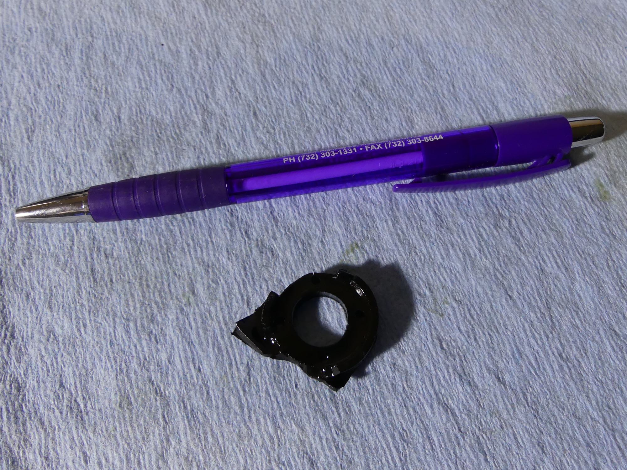 Mystery time. I found two of these parts scattered in the head (one towards the front, the other towards the rear). I have no idea what they are but surmise they are part of the valve cover. I definitely need to figure out where they're from so I can replace whatever has broken. |
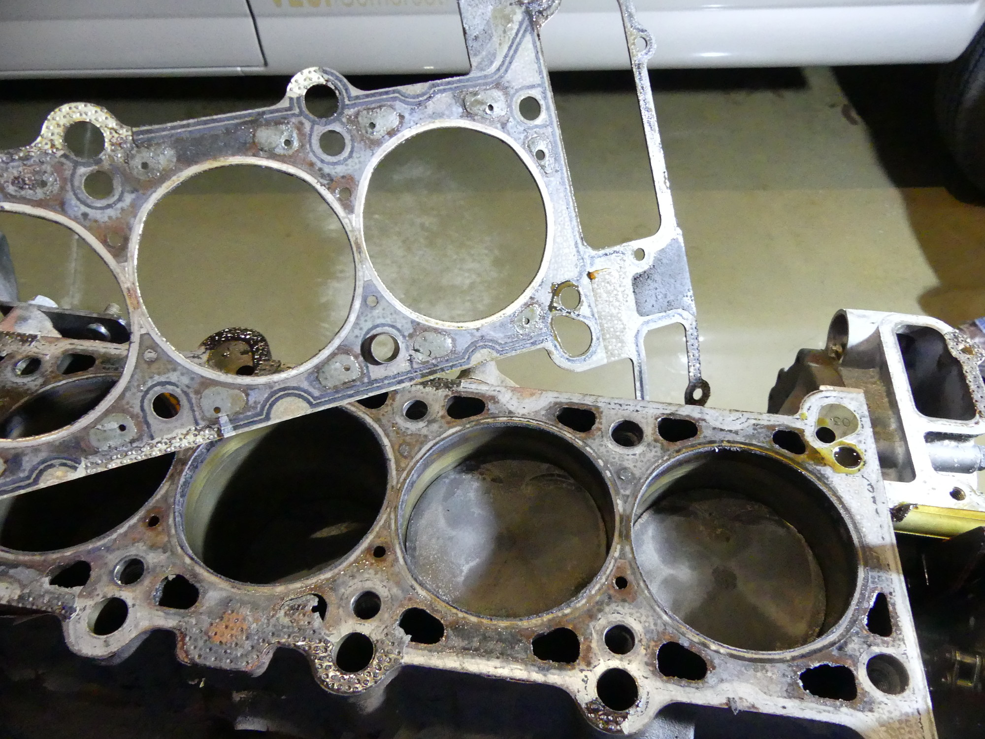 The head gasket gave up a bit of a fight but I ultimately managed to remove it from the block. While not particularly attractive in this state it's pretty clear that it held up for 265K miles. Other than regular coolant flushes I can't attribute any particular maintenance practice to this kind of longevity. |
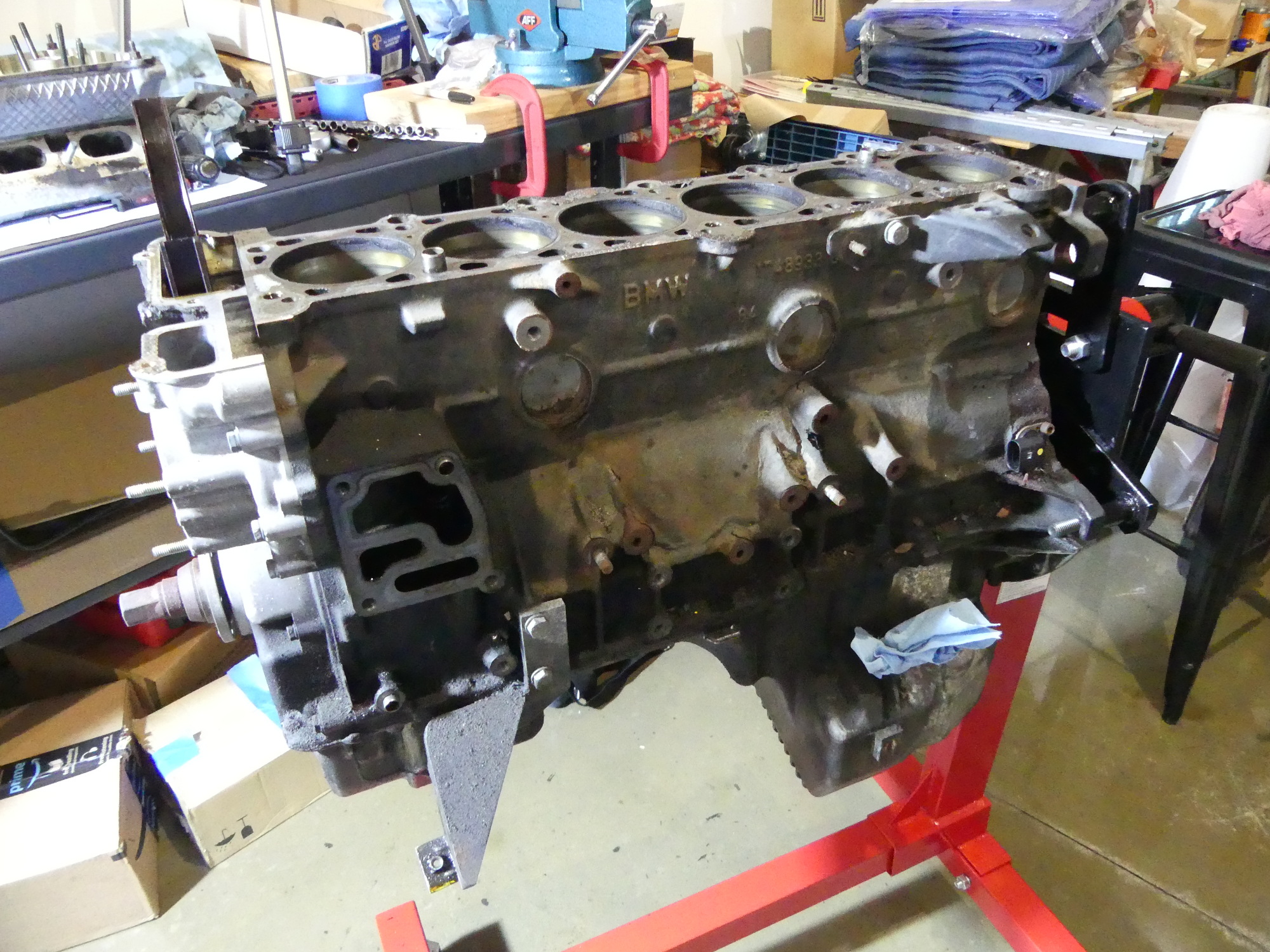 At the end of my work day this is the state of the block. Next up I'll send the block out to Autohead and get started disassembling and blueprinting the bottom end. All for now. |
The head gasket appeared to be in good shape, particularly over the web between cylinders. The tops of the pistons confirmed the diagnosis provided by the spark plugs -- a normal degree of carbon buildup across all cylinders. Had one cylinder been cleaner than the others I might have suspected coolant was leaking into the cylinder from either a head gasket failure or crack in the head.
Next Up
Next up is packaging the head for delivery, separately packaging the springs and retainers, and sending both boxes to Autohead for the overhaul. After that is complete I have to place another large parts order with my dealer and then come back to disassemble the block. That process shouldn't take long but I expect my blueprinting efforts to take the better part of a day. As a result I'm hoping to deliver the block and other parts to the machinist on Thursday or Friday, and then start working on the body once the parts come in.