


Obsolescence Guaranteed PiDP-8/I Kit Build
I can hear the teletype
now.
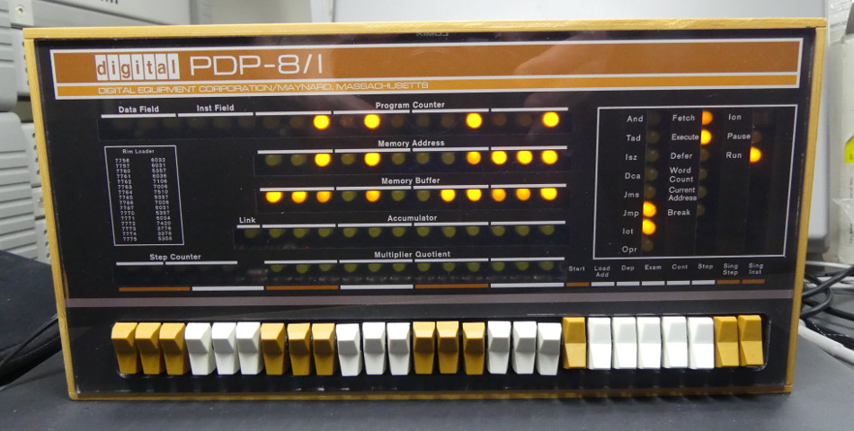
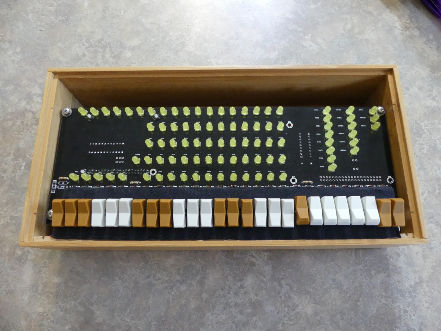
Behold, my completed PiDP-8/I.
As a fan of Steve Gibson's Security Now podcast for the last few years I knew that Steve had a fascination with the PDP8. In the background of his videos are three PDP8 replica kits he purchased from a now dormant project. The advantage of these kits were the authenticity of the hardware -- they were based on the Harris HD6120 "PDP8 on a Chip".
Unfortunately these kits were ~$600 when they were available, and thus outside the "fun budgets" of many hard-core techies like me. Still, I always hoped to own something like this as PDP8s were popular computers when I was born and I have spent my career working with computers, including embedded systems. It seemed appropriate that I own one to learn how computing was done at the time of the moon landings.
While listening to Security Now in the spring of 2016 I learned of a new PDP8 project. Oscar from Obsolescence Guaranteed decided to launch a project to build a smaller replica faceplate of the PDP8 called the PiDP8/i. While driven by a Raspberry PI and a software-based PDP8 simulator (simh) rather than the "authentic" hardware of the more expensive kit, at $140 + shipping Oscar's kit promised to be a far more reasonably priced example of retro computing technology. I got on a Oscar's list to buy the kit in mid 2016 and after some delays I took delivery late in 2016.
Kit Overview
The kit consists of a wooden enclosure (made of bamboo), some wood blocks to mount the PCB to the enclosure and all the electronics parts, exclusive of the Raspberry Pi, needed to get the unit operational.
One of the things that initially attracted me to the kit was the requirement for a Pi, since I had several laying around from prior projects so I figured I could put one of those to use and avoid the cost of a Pi. Unfortunately, in my rush to spend as little time on this as practical I discovered after the kit arrived that I misinterpreted the requirements. The kit required a PI version 2 or PI zero and all I had were second generation Version 1 PIs. I wanted remote access to the unit so that meant I had to buy a PI Version 2. The PI version 3 was available at this time, incidentally, but I had heard of various software issues with that board unrelated to the PiDP8-I project so I elected to avoid it.
The kit arrived in one piece, mostly because it was well packaged. Each piece including the PCB was individually wrapped for protection. The one thing I did not like, however, was receiving all of the electronics components in a standard #10 envelope. Not only was this not resealable but it was hardly proper anti-static protection for the devices.
The single IC in the kit was wrapped in what appeared to be a small section of anti-static bag material taped together, so Oscar was clearly aware of the ESD risk, yet he failed to implement a proper solution for all components. I know this was a low-budget kit but it would have cost only a few dollars to include a proper, resealable ESD bag for these parts and deliver the DIP IC pressed into a small section of anti-static foam.
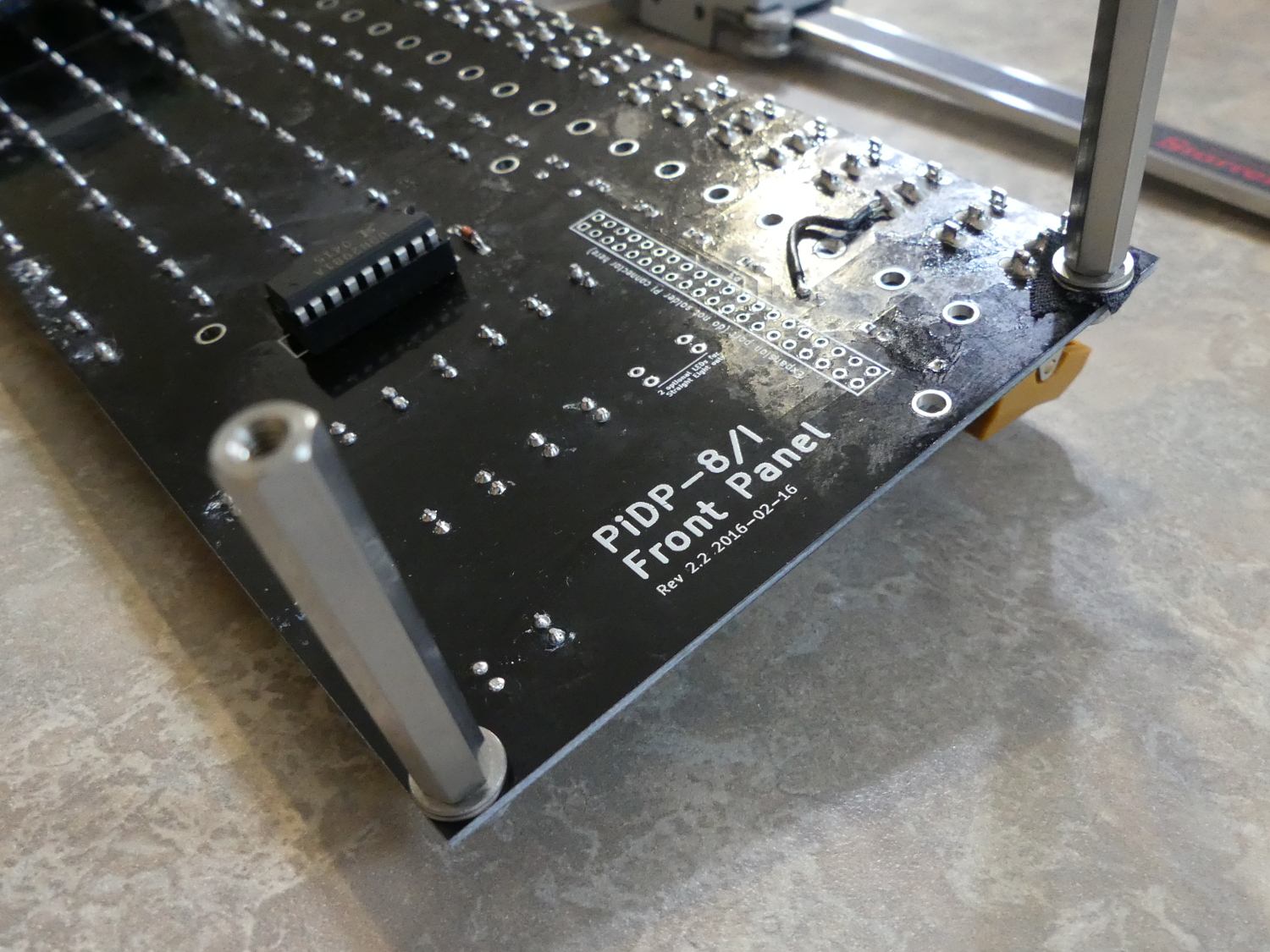 This shows the underside of the PCB while I was test fitting the standoffs. I found I had to use two M3 washers (0.8mm each) plus the 40mm standoffs to adjust the height. M3 screws 10mm in length were necessary here. Longer screws cannot be used because the standoffs have insufficient threads. |
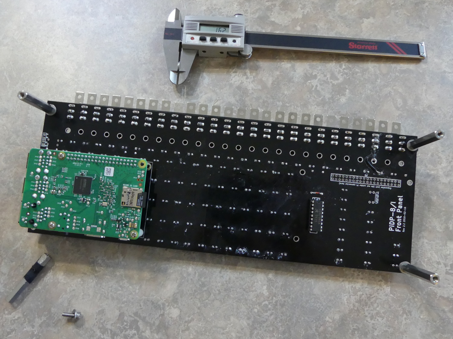 I installed the Version 2 PI but as you can see the PCB mounting hole is a bit too close to the corner of the PI so I had to modify one of the standoffs slightly. I wrapped some fabric tape around the notch in the standoff for insulation and to protect my fingers from the sharp edges that resulted. |
 Taken before I applied decorative fabric tape to the switch mounting tabs you can see how they sit quite distance off the PCB. Also notice that I used a single washer on the top of the PCB so the PCB is now sandwiched between washers, making the entire assembly a lot stronger. |
Component Testing
One thing that the instructions do not emphasize, but I strongly recommend, is testing of all components. I used my Rigol bench power supply with current limited to 10ma to test all the LEDs but this could just as easily be done with one of the provided 390 ohm resistors in series with each LED. I also used my Fluke 87 multimeter in diode mode to test all the diodes for the proper drop. And finally, I again used the multimeter in resistance mode to verify the value of all resistors.
Why is this important? It reduces the number of variables involved and points any potential failure away from these components. The good news is, intentional or not, Oscar included a couple extra LEDs and resistors in the kit. Those would come in handy later.
PCB Assembly and Testing
The PCB assembly and testing went pretty much as expected. The documentation labored to point out the correct orientation of the LEDs, but this would not have been necessary had Oscar simply used the industry standard symbol / footprint for a 5mm LED on the silkscreen. This symbol mirrors the shape of the LED, which is a circle with a flat on one side indicating the cathode, and would eliminate any possible confusion for all but the blind.
One glitch I experienced with the board was during the switch installation. Despite the warnings in the instructions to pay attention, I was multi-tasking and on the phone during this phase of the assembly and accidentally wound up installing one switch in the wrong location. I managed to catch the error early enough but nevertheless had to desolder one of the switches. The pads used for the switch vias are oval and have a very thin sliver of copper on the "long" sides of the switch terminals. Unfortunately, as I feared might happen, I wound up lifting one of the pads on that switch. And because Oscar routed the signal trace to the "thin" portion of the pad rather than the thicker side portion this wound up breaking the circuit and I had to add a white wire from that switch terminal to the associated via to restore conductivity.
The other glitch became obvious after I put the completed board into test mode with the software provided on the Tangentsoft distribution (which became the official software repository in December 2016). This test command revealed that while all the switches (including the one for which I applied my white wire fix) worked as expected, the Pause LED did not work. I pulled that out, replaced it with one of the extras provided in the kit (thanks for thinking ahead Oscar!) and continued with testing. I immediately realized the cause: I had been doing some lead-free rework a few weeks ago and left that soldering temperature set in my iron. I soldered a couple LEDs before I realized I needed to bring down the temperature as I was working with Tin/Lead solder for this project. In short, I lingered too long on this LED as I developed the technique required to solder them in straight with an iron tweaked too high. It happens. In any case, I replaced the LED and tested it again to find the entire panel working as expected.
Why is it is important to include a few extra LEDs (in particular) for a project like this? LEDs are actually quite difficult to match in both color (wavelength) and intensity (luminosity). Purchase the same wavelength LED from three different manufacturers and you will likely get three subtly different colors (and more noticeably) brightness levels for a given current. Had I been forced to acquire replacement LEDs on my own I doubt they would have matched.
Power Supply
The instructions indicated that the project could be powered from either the micro USB port on the PI or by an external 5V power supply soldered directly to the project PCB (not the PI). I wound up powering the board during the initial testing using the micro USB cable plugged into a 110V / USB charging adapter and ultimately transitioned to an old 5V 2.5A wall wart I salvaged from a decommissioned Roku.
 Here is a closeup of the result of the standoff modification. As you can tell I didn't need to cut that much off the standoff to make this work. Not the ideal scenario, but it worked, and allowed me to toss the blocks of wood. Access to the PCB for maintenance should be a breeze. |
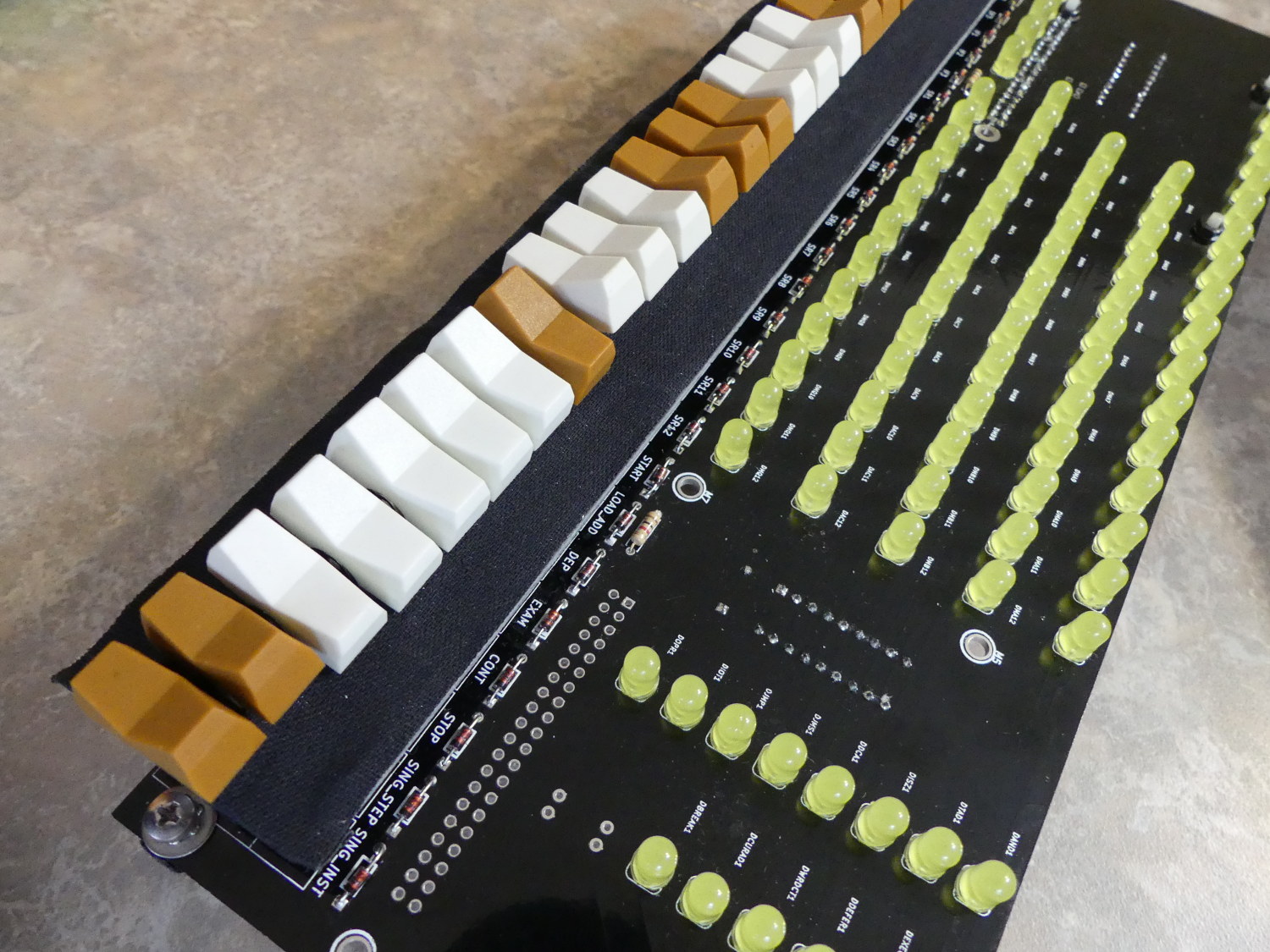 I decided to cover the switch tabs with Scotch brand fabric tape as opposed to the vinyl electrical tape most people seem to use. This almost looks like a factory dust shield of the era! The fabric tape is not reflective like the vinyl tape can be so it fades into the background as required. |
 The switch tabs are designed to rest on the small ledge milled into the chassis. The problem is if left as is the ridge is not deep enough to accommodate the switch tabs and fabric tape. The end result would be the acrylic panel sitting above the front face of the chassis. Some additional milling fixes the problem. |
I tested the external power supply before I integrated it with the project and found it delivering 5.39V (!) That is outside the acceptable tolerance for 5V power supplies but I knew it would likely drop somewhat with the load of the PI and this board. During the initial power up using the external supply I watched carefully for "LED glow" as indicated in the instructions but did not see any, thus I did NOT cut the trace bypassing the diode per the instructions. Your mileage may vary.
The downside to the external power supply method is the fact that most power supplies use ~18-20 gauge wire and the vias on the PCB for GND and 5V are too small to accept this wire. So I had to solder 24 AWG pigtails to the board and bell-splice and solder those to the larger power supply wires.
Chassis
If there's a part of this project that is decidedly low rent, it's the chassis. I realize that given Oscar's cost constraints he was forced to accept some compromises. I am also aware of the "retro" wooden look Oscar was going for here, but I would have gladly paid more money for a properly engineered metal chassis with all holes pre-drilled and slots ore-milled. Since that wasn't to be, I made do with the chassis provided but it was not without snags:
-
The first issue related to my selection of the Raspberry PI Version 2. The unit is much bigger than the zero and so it prevents the small wood block from fitting where the instructions (and common sense) require it to be in order to catch the mounting screw. In short, it was not possible to use the small wood block in this location.
-
The second issue appeared when I test fit the long wood mounting block to the location under the PCB per the instructions. The white wire I added to fix the lifted switch pad was small but big enough to cause the block to sit away from the PCB in that area. That would have forced the PCB to sit at an angle (left to right) and have been obvious in the height of the switches protruding through the acrylic face.
-
The chassis comes with a roughly 3mm recess milled into the front face. The acrylic panel is designed to fit into this recess and produce a flush finished appearance. The instructions state that the PCB should be positioned in the chassis such that the metal tabs of the switches sit on top of that recess. Unfortunately, this design did not accommodate the fact that the switch mounting tabs are 0.8mm thick. A test fitting of the acrylic panel to the chassis with the PCB mounted as recommended revealed the problem - the acrylic sat a good 1mm above the wood.
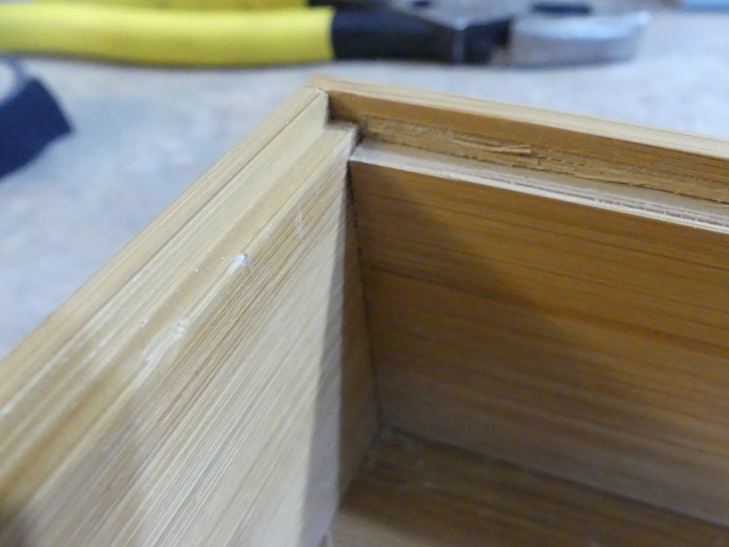 A closeup of the completed milling of the recess in the front of the chassis, as required to accommodate the thickness of the switch mounting tabs and tape. I managed to cut about 1.5mm out with a sharp knife. If you attempt this modification, be exceptionally careful. It's easy to slice your hand open if you slip! |
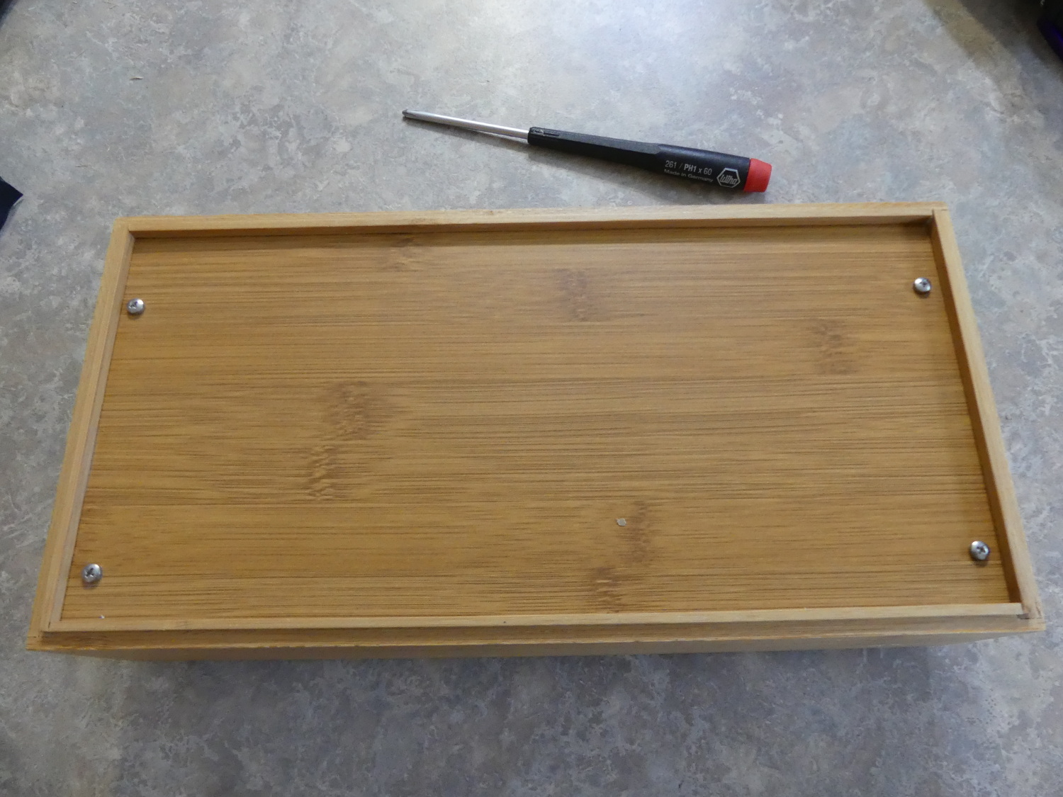 After test fitting the PCB with standoffs in the chassis I marked the approximate location of the holes on the inside rear of the chassis and then drilled them out from the front before finishing them up from the rear. I loosely fit the screws to make sure they would all line up and then tightened them, securing the board to the chassis. |
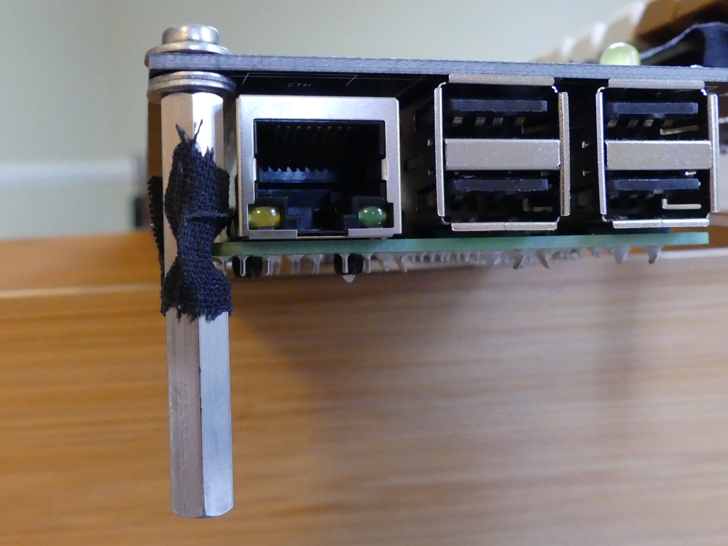
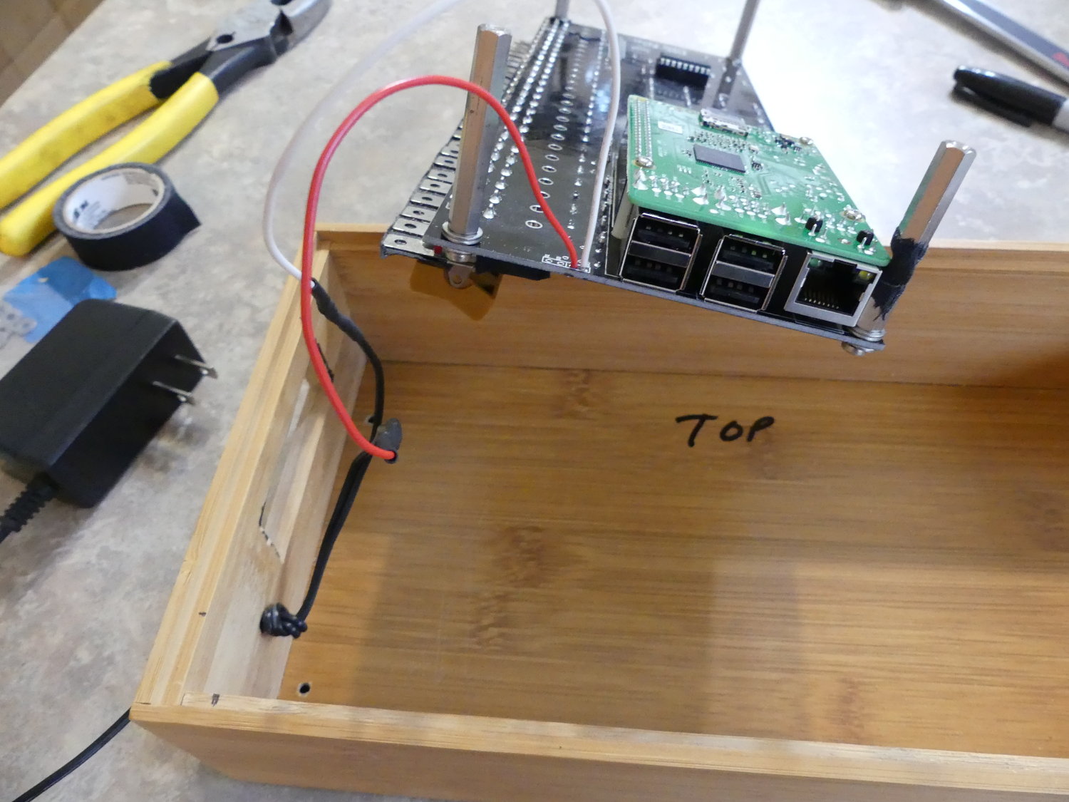 This shows the simple but effective power supply connections. I had plans to use a connector on the leads coming from the PCB so I could disconnect it from the chassis for maintenance but this will do. Here you can also see the milled slow that exposes the PI's USB and Ethernet ports. |
I decided to fix issues #1 and #2 by changing the mounting method. I wound up buying (4) 40mm threaded M3 standoffs, mounting the PCB to the chassis using those standoffs and a few washers to fine tune the height of the PCB relative to the front panel.
This mounting solution was not without its problems -- the mounting hole in the same corner as the PI is simply too close to it. This caused the standoff to interfere with the PI's PCB. I solved that problem by gripping the standoff in a pair of pliers and using a sabre saw with a 24 TPI metal cutting blade to cut a small, ~2mm deep slot in the standoff sufficient to clear the PI's PCB. This of course compromised the strength of the standoff slightly, but inconsequentially. After all, it's not holding up a battleship. I then wrapped the slot cut in the standoff with some tape for insulation before installing it.
I fixed issue #3 by using a new, sharp blade in a box cutter to carve enough material from the recess (about 1.5mm) to allow for the additional thickness of both the metal switch tabs (0.8mm) and the black fabric tape (roughly 0.5mm) I used for cosmetic reasons to hide the tabs. Incidentally, the fabric tape I used is made by Scotch and is the perfect tape for this job. It molds better to the imperfect heights of the switch tabs and is less glossy in appearance than traditional vinyl electrical tape, so it fades into the background. I love the look.
I drilled four holes in the back face of the chassis to accept the mounting screws, and used a drill in combination with my sabre saw to cut out the slot required in the side of the chassis to accept Ethernet and USB connections to the PI. I wrapped up the modification of the chassis with another small hole designed to accept the power cord coming from the wall wart. I initially had plans to use a DC barrel jack to mate with the factory Roku power supply barrel connector but I could not find a jack capable of tolerating the nearly 7 mm thick sides of the chassis. So I just punted and tied a couple knots in the cable on both sides of the chassis wall to prevent the cable from moving in or out under strain. Not my finest moment in assembly, but it's not stupid if it works.
Software Distribution
Although Oscar provides a read-to-use raspian-based distribution for the project it hasn't been updated a while and he has since blessed the Tangentsoft site as the official repository for the PiDP-8i software repository.
I therefore used the latest binary distribution available at the time and found it worked out of the box. Incidentally, at the time they were developing a "lamp simulator" version that apparently attempts to emulate the slow rise and fall time of the incandescent bulbs present on the original PDP8, but that version requires additional processing power I was unwilling to dedicate to the PiDP-8i display so I stuck with the original version.
The Tangentsoft distribution comes loaded with a bunch of PDP8 programs, most of which I had not researched as this writing. The one program I was looking for was Steve Gibson's "Deep Thought", which is designed to blink the front panel lights in a pointless yet strangely meaningful way, but alas it had not been ported. Part of this apparently has to do with how the front panel switches are implemented on the PI version as compared to the hardware-interrupt based switches of the "authentic" PDP8 replica.
The simulator that loads OS/8 and drives the front panel display is loaded automatically as a service during the boot of the Raspberry PI. Although the PI's own status LEDs light up immediately upon application of power, it takes a good 40 seconds before the simulator launches and starts diddling bits that drive the LEDs. Once up and running the display doesn't do much until you start interacting with the simulator on its console or running a program.
Initial Software Configuration
My initial testing was done with the project PCB and PI outside the chassis and with an HDMI monitor and USB mouse & keyboard connected directly to the PI. I used this to login so I could configure the system.
First I made some account changes.
I created another account with the same credentials as I use for several internal computers just so I wouldn't have to type the ridiculous pidp8i username all the time.
$ adduser
I changed the pidp8i account password because the default is annoying to type.
$ passwd
I then gave the root account a password so I could use the root account directory vs. sudo:
$ sudo passwd root
With access to the root account I launched the raspian configuration utility:
$ su -
# raspi-config
I used this primarily to extend the size of the filesystem which is fixed at 2GB by default to the size of the MicroSD card I used for the project (8GB). This is not critical for any application that strictly involves use of the PDP8 simulator but as I had other plans for the host I felt it was necessary.
I also used it to enable sshd for remote access, since that is disabled by default for security reasons.
I wrapped up the initial software configuration by running the pidp8i-test program. This application is provided to validate the integrity of the PCB assembly process. It cycles each row and column of LEDs, cycles through each individual LED in a continuous loop, and also allows you to operate each switch to verify its operation.
My First PDP8 Interactions
To enter the PDP8 simulator I simply typed:
$ pidp8i
This brings up the already-running PDP8 OS/8 shell and its decimal / period prompt (.)
To see what files are on the filesystem I typed:
. DIR
This produces a most pleasant effect on the front panel and I must admit to spending a full minute simply typing DIR over and over again while glancing over at it.
For something a bit more practical, I ran Adventure, the first text adventure game:
. RUN RKB0 ADVENT
The loop that waits for input in this game also produces a nice cycling pattern of the accumulator LEDs that is suitable for parties. Just park this unit in the corner running Adventure and just wait for all the hot chicks in the room to flock to you, wanting to have your babies. :)

To detach from the OS/8 shell and get back to the Linux shell without terminating the simulator:
. ctrl-a d
...which is to say, press the CTRL and A keys together simulaneously, then release them before pressing the D key. This awesomeness is, incidentally, brought to you by screen.
To reattach to the OS/8 shell, simply type pidp8i again. Finally, to shut the shut the simulator down from the OS/8 prompt type:
. ctrl-e
simh> quit
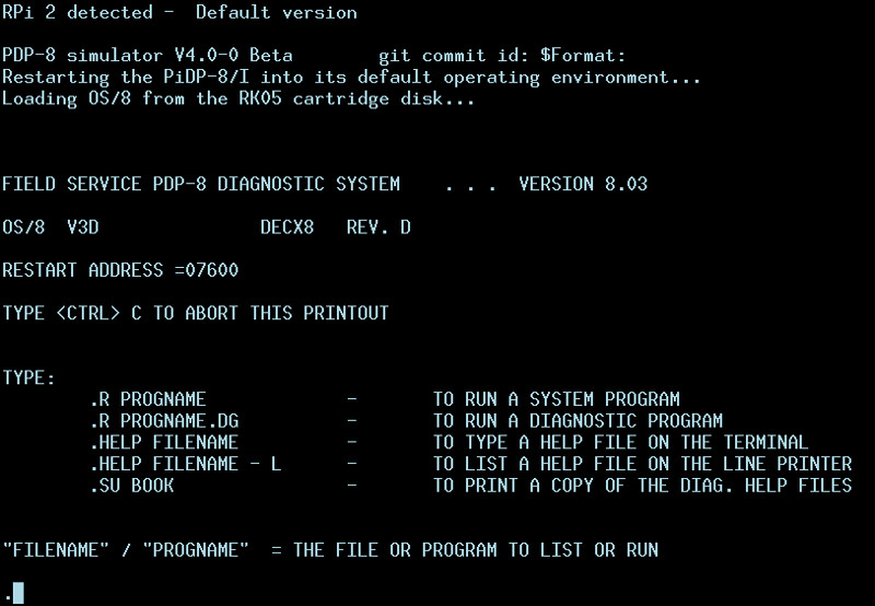
The OS/8 shell in all its glory:
Summary of Recommended Kit Enhancements
Just in case Oscar is considering doing another run of these kits I figured I'd make several recommendations for improvements:
-
Use the industry standard silkscreen footprint for the 5MM LEDs to aid orientation.
-
Engineer a proper chassis for the kit. If you don't have the CAD software and experience to do this, employ someone who does. I may be willing to tackle the project given a sufficiently large order and advance notice.
-
Move the mounting holes on the top of the board up a few millimeters and extend the height of the PCB as needed to accommodate OR move the PI down a few millimeters. That will allow the use of standoffs like the ones I used to mount the board but without any required modifications to accommodate the full size Raspberry PI (Version 2 or 3).
-
Standardize all PCB mounting holes to use M3 hardware. There is a much larger assortment of M3 hardware than M2.5. In fact I could not find any standoffs of the length required in M2.5. Incidentally, the current mounting holes fit M3 screws, but just barely.
-
Increase the size of the vias on the PCB used for external power to accommodate 18AWG wire...or perhaps more to the point, add vias for power so that the serial port wiring remains the same. Also increase the size of the annular ring of these vias. Slivers of copper will lift from the fiberglass substrate during rework.
-
Increase the size of the pads for the switches. The sliver of copper on the flat sides of the switch vias is too small and does in fact lift during rework because there's not enough copper to bond to the substrate in any meaningful way. Route the traces going to the switch pads such that they hit the pads on the thickest part of the pad (i.e. the sides). Do not route traces in between the switch pads as this begs for issues during rework of the switches and prevents increasing the size of the pads as needed for reliable rework. If routing cannot be accomplished on 2 layers, provide vias as needed to allow the insertion of solid wire jumpers.
-
Provide the manufacturer name and part number for the LEDs used in the kit, just in case replacements must be sourced locally. If you're not using name-brand LEDs, switch to them so they can be sourced at legitimate distributors like Digikey and Mouser.
-
Provide all parts in a resealable anti-static bag -- not an envelope.
Conclusion
This was a fun project, despite having basically no time to dedicate to the task. I found the basic electronics of the kit adequate but the chassis lacking. I've had computer-savvy and neophytes alike over to visit and the kit has become quite the conversation piece. Total time for the build was around 4 hours.
I don't know if Oscar will do another run of these kits but I hope if he does he implements at least some of my requested improvements -- the most important of which are a move to standoffs for mounting and a pre-milled chassis. This will make the kit a lot easier to assemble.