


Saturday, May 18, 2024
Revision 14: Mechanical Design Changes
Not long after I sent the architect revision 12 I began looking at some finer details of the design including the HVAC systems. I knew up front that this building would likely be host to three and possibly four HVAC zones, but what was not exactly clear was the technology I'd use.
Ductless mini-splits and traditional ducted systems each have their own merits. Following some research I realized that mini-splits do not provide sufficient air circulation throughout the structure or the ability to properly filter the air. Mini-split filters are, like most integrated furnace filters, designed only to protect the equipment, and do very little to improve interior air quality.
If I wanted to install a MERV 16 filter or something similar and have that filter work for the entire zone, I figured I'd need to deploy a ducted system. This involved examining exactly how I'd route the ducts through the structure. I then realized that while having a dedicated mechanical room made great sense, routing ductwork from that room across the garage and into the living space would not be cost efficient and would likely run afoul of building codes that prohibit running ductwork through spaces like garages that are potentially contaminated with carbon monoxide. No ductwork is perfectly sealed, of course.
For these reasons I decided to revise the plan to provide a smaller mechanical room to serve each "shed roof" area, with access to the equipment provided via the garage using a dual metal door -- that way trades who come to fix the equipment can roll their truck right into the garage and park it directly adjacent to the mechanical room, rather than walking tools and service equipment into the living space(s).
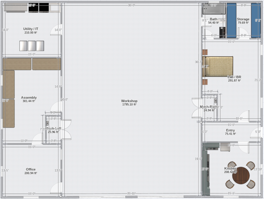
Each mechanical room will likely contain:
-
An air handler associated with an air-to-air heat pump that will provide primary cooling and heating via traditional forced-air ductwork.
-
A dehumidifer system integrated into the forced air ductwork, primarily to reduce humidity in the shoulder seasons.
-
MERV-rated filters integrated into the forced air ductwork.
-
An air to water heat pump (aka a heat pump water heater) or a LP gas-fired tankless hot water heater to feed the hydronic heating system.
-
A PEX manifold to provide zone control for each hydronic heating zone.
As I've learned more about hydronics, the generally lower water temperatures involved, and the operating costs and government subsidies associated with heat pump water heaters, I've considered using a heat pump water heater for the hydronic system. The downside is that a heat pump water heater extracts heat from the ambient air and some form of continuous air recirculation within the mechanical rooms will be necessary. A single air change per hour is all that's necessary and on a room this small this translates into approximately 5 CFM, which can be easily handled by a small electric fan and vents in the access doors.
Alternatively, I can go back to my original plan and install a simple resistive element water heater or leverage the LP tank to feed a gas-fired tankless system. Due to the relatively short heating system on the mountain I shouldn't use much electricity or LP in any case.
If you're wondering why I am not considering an electric tankless water heater it's a simple matter of power budget. These systems can draw well in excess of 70A, and my plan is to size the inverters for the maximum average load rather than the peak load to reduce cost. When inverters are presented with a load beyond their rated output they drop back to grid power. If that happens here and there, that's fine, but I don't want it happening on a frequent basis, since the transition to grid will take all the other loads with it, and that defeats the purpose of installing hybrid inverters and the battery systems to feed them.Regardless which heating plant I elect to use, I think the biggest challenge will be finding a subcontractor that is familiar with hydronic heating systems, as I can't imagine they are particularly popular in the south for obvious reasons. But I'll tackle that problem with the builder when the time comes.
You may also notice that I changed the location of the bathroom and closet, which was motivated by my desire to locate the new mechanical rooms in the approximate center of the space. This in turn was dictated by some research that indicated ductwork is most efficient when driven in parallel, i.e. when there are two paths split out from an air handler in a central location, in something resembling a "Y" format. This is because frictional losses are directly proportional to duct length, so the shorter the ducts, the lower the frictional losses for the span. This, in turn, reduces the size of the blower required to achieve the desired airflow in CFM.