


1996-1999 BMW E36
Automatic Climate Control Repair DIY
When, not if, the automatic climate controller in your E36 BMW begins to turn
on and off randomly you can either replace the unit for $600 or conduct the
component level repair outlined here for $0.50 and a couple hours of your day.
Introduction
The body electronics of a BMW are generally reliable but the HVAC controller has one weak spot in its design that results in the controller randomly turning on and off. When this problem occurs the end result is no heat or air conditioning.
This problem occurred first on my car when it was five years old. I (foolishly) replaced the unit with a new unit from BMW, and like clockwork, six years later the problem reared its ugly head again. This proves that not only is the design flawed, but this is one of those rare cases where buying new isn't the best solution (unless, of course, you don't mind replacing the entire unit to the tune of $600 every 5-7 years). This DIY outlines the process required to conduct a component-level repair of the automatic HVAC controller of an E36 BMW to address this problem.
Please note that while I dabble in electronics I am not an electrical engineer, I do not have the schematics for the logic boards in the device, and I did not originally identify the part that needs to be replaced. This DIY merely represents my experience with the repair.
Troubleshooting
The most obvious symptom of a failing HVAC controller is the intermittent operation of the unit. This condition is easily noticed when:
- The controller's display backlighting flickers on and off randomly
- One or more LEDs may be illuminated but none of the buttons work
- The blower motor does not run at all
- The air conditioning does not work
- The auxiliary cooling fan runs inappropriately (like when the A/C is off and the engine is cold in wintertime)
For the record, the car appears to run fine with the HVAC controller connected but not operational so a failure of this part should not take the car out of service.
Note that intermittent operation of the blower motor without any of the above symptoms is likely related to a faulty HVAC blower motor relay or the blower motor itself. See my HVAC Blower Motor DIY for more information.
Prerequisites
Tools
- 13 mm shallow socket and ratchet
- T7 Torx Driver
- Small slotted screwdriver (slot < 1/4"), or an equivalently-sized dowel about 2" long and a hammer
- Plasma rifle...err..soldering iron in the 25-50 watt range equipped with fine point tip
- 60/40 Tin/Lead Rosin Core Solder, 0.31" diameter (Kester "44" or equivalent)
- Desoldering bulb OR manual pump OR station
- [Optional] Small workbench vice with "soft jaws" (foam padded)
Parts
- 0.47µF 50V Tantalum Capacitor
- [Optional] Temperature sensor fan (BMW Part # 67-32-8-378-663)
Capacitor Part Selection Update: Since writing this article and repairing my own HVAC controller with the above part in 2010 I've learned that tantalum capacitors are notorious for their low reliability. While I haven't had any problems with the part I installed and you can certainly use that if you want to keep things simple, a film type may be a better option.
Film capacitors are typically provided in either a rectangular plastic package or dipped in epoxy. Looking back, the original capacitor package was a box. This does not guarantee that it was a film type but it's likely given its suspected function in EMI suppression within this circuit. Therefore it's probably best to replace the failed part with a 0.47uf film type capacitor.
Since parts are frequently obsoleted I recommend searching Mouser or Digikey for a 0.47uf film capacitor rated for at least 30V. The lower the tolerance the better (5% being lower than 10% or 20%, naturally), but you'll pay extra for that...not that any of these parts will break the bank. Using a part rated for a higher voltage is acceptable but the package sizes increase dramatically with voltage so it's best to stick with something about double the maximum expected voltage (14*2=28V) and certainly never below that or failure will be more likely.
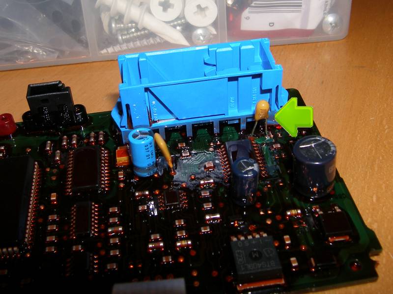
The lead spacing should be 5mm but don't quote me, as I did not measure it when I had the unit apart. Lead spacing is more critical for the short-leaded rectangular plastic packages and less of an issue for the epoxy-dipped parts since the leads are typically longer and can be bent to accommodate the hole spacing in the PCB, similar to what is shown in the picture at the top of this article. Quality manufacturers include Vishay and Kemet.
Removal / Disassembly Procedure
- Disconnect the negative battery cable from the battery terminal. A short 13mm socket and ratchet will be required. Insulate the terminal in a work glove or otherwise wrap it such that it will not contact either the battery terminal or any nearby metal including the vehicle body.
- Move the gear selector for clearance purposes. Apply the parking brake to ensure the vehicle will not roll, press and hold the brake pedal for good measure and then move the gear selector away from the dashboard so the OBC can be removed without hitting the selector. In manual transmission equipped vehicles this will likely be as easy as moving the selector into neutral. In automatic transmissions equipped vehicles, however, it is necessary to turn the key to position 1 (in addition to stepping on the brake pedal) to disable the interlock before the selector will move aft.
- Remove the OBC. Turn the palm of your dominant hand face up and touch the roof of the pocket just below the OBC to find a hole. Put your finger in the hole and press directly upward to reveal the OBC's spring-loaded plastic locking tab. The tab won't depress much but it must be fully depressed to release the OBC. While pressing the tab upward, simultaneously pull the tab (and thus the OBC) toward you until the unit begins to move forward and is thus unlocked. Once the OBC is unlocked, put your finger behind the OBC and pull the unit toward you to remove it from the dashboard. The OBC may remain attached to the vehicle.
- Return the vehicle to first gear or Park, as appropriate to prevent the vehicle from rolling and remove the key from the ignition if appropriate.
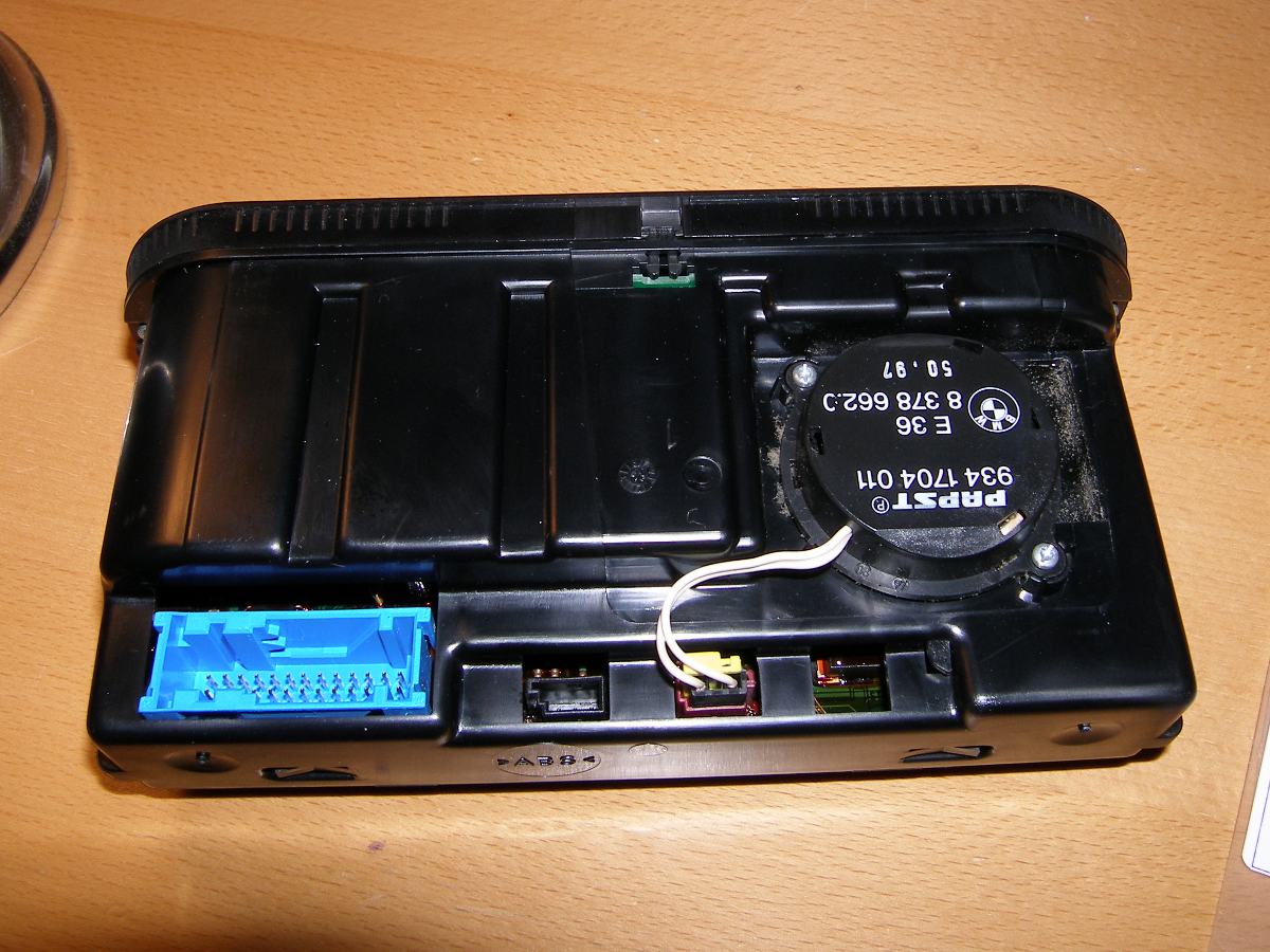
- Remove the HVAC Controller. Reach into the hole in the dash left by the OBC and push on the back of the controller to push it out of the dashboard. This will expose two cables that must be disconnected. The first cable is a large bundle of wires terminated with a large blue connector. To remove the connector, slide the white locking lever down and away from the cable end so that it mates with the case of the controller. The second cable is a simple multi-conductor cable. Firmly grasp the connector and pull it from the socket on the controller. Do NOT pull either connector by the wires.
- Prepare a workspace suitable for electronics rework including ESD protection. Make sure your workspace has bright lighting, a magnifying lens, soldering and desoldering equipment, and most importantly, an effective means to prevent electrostatic discharge (ESD). This should, at a minimum, consist of a properly grounded wrist strap and an anti-static mat. If you attempt to do this repair in the winter or at any time the relative humidity is lower than about 60%, a very real risk of ESD exists. If ESD occurs while holding either circuit board permanent damage to the controller electronics may occur. For reference, I conducted this repair in December with an indoor relative humidity of 45% and I noticed several ESD events while I was preparing the workspace. Don't think ESD won't happen to you, because by the time you notice it, the damage is already done.
- Remove the temperature sensor fan. The fan must be removed before disassembling the unit, but it need not be replaced unless the fan does not spin freely. At $125 the fan is not exactly inexpensive but now is the time to replace it if necessary, but if you do remove it, I strongly recommend taking it outside and using a can of compressed air to thoroughly clean it of the dust build up. This will make the fan more efficient and help prolong the life of the motor.
- Remove the controller faceplate. Place the controller on its face and remove two T7 torx screws holding the chassis to the faceplate. Once these screws are removed, the only thing holding the faceplate to the chassis is a couple of locking tabs integrated into the faceplate that insert into notches on the top and bottom center of the case.
- Detach the front logic board from the case. Push the front logic board (the one with the display) up slightly and then pull the bottom of the board (near the two ribbon cables) out from the case. Once the front logic board is removed, it will fold away from the case but will remain attached to the inner logic board via two ribbon cables. Be very careful not to stretch those cables.
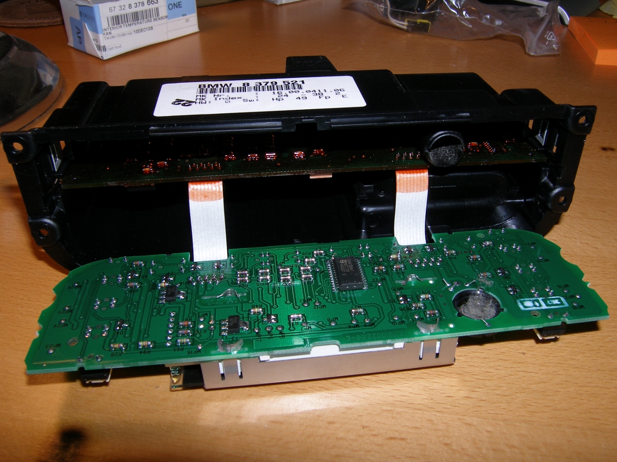
- Remove the rear logic board from the case. This is the hardest part of the job. Locate two small rectangular holes on each side of the case into which small tongues milled into the circuit board. Also locate two small holes on the back of the case through which the edge of the inner logic board is visible. The goal of this step is to warp the case enough to allow the tongues to release and the inner logic board to slide out of the case. Begin by squeezing the side opposite the fan in one hand while you gently grasp the inner logic board in a "safe" place (so as to place minimum force on any components on the board) and pull slightly. This will cock the board in the case. Then, without relocking that tab accidentally, squeeze the other side of the case and pull the logic board on that side. If the side refuses to budge (and it might), then carefully push the end of a slotted screwdriver through the corresponding hole in the rear of the case at an angle with the edge of the logic board (to prevent it from slipping) and gently push the screwdriver enough to help push the logic board out of the case. As another DIYer said, "this is both easier and harder than it sounds".
- Desolder the existing capacitor. If you have some soldering flux, now would be a good time to use some to help the solder to reflow, but I just applied a bit of new solder to get some of the flux from it before sucking it all away with a simple desoldering bulb I had handy. Worked like a charm. I then used a pair of small long nose pliers to grab the part from the component side of the board and then individually heated each lead until they pulled away from the board. When the part was removed I used a small pick to clear the holes of a few stray bits of solder before I prepared to install the new part.
- Install the new capacitor. Tantalum capacitors are polarized just like electrolytics. It is therefore important to observe polarity during the installation process. Follow up by cutting any excess lead length from the solder side of the board. For the record, I installed the positive lead (labled with a "+" and a line pointing to the positive lead) on the side closest to the edge of the logic board (or the side opposite the nearby surface-mounted IC). A quick but thorough heating of each lead and the application of a small amount of solder permanently installed the part.
Installation / Reassembly Procedure
- Clean the case and logic boards of dust. Using a can of compressed air, thoroughly clean both logic boards, the temperature sensor fan, and fan duct of any dust.
- Insert the rear logic board into the slot in the case. Correctly orient and install the temperature sensor fan duct through the hole in the logic board and then carefully insert the logic board into the slot in the case. Push it until you hear the locking tabs in the board snap into the holes on the side of the case.
- Install the temperature sensor fan. Note that if you chose to replace the fan, the new part will come with two screws and some plastic spacers. The screws are similar to the originals but about 2mm longer to accommodate the spacers. Don't mix them up. Make sure the yellow fan connector is fully seated in the red socket on the controller.
- Attach the front logic board to the case. Insert one end and then push the other end in to secure it.
- Install the faceplate. First snap it back into place and then install the four screws to secure it.
- Install the controller in the vehicle. Attach both cables, engage the white connector lock and then simply (but carefully) press the controller back into its slot in the dashboard.
- Install the OBC. This is another press-fit.
- Attach the negative battery cable to the battery terminal.
- Turn the ignition key to position two to test controller functionality.
Procedure Highlights
 Gaining access to the HVAC controller requires removal of the OBC. Easy if you know what to do. |
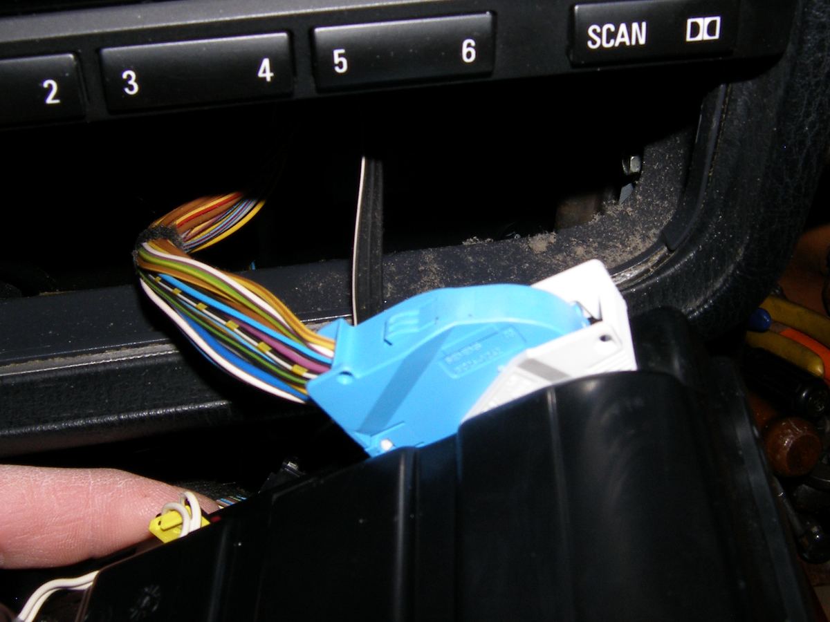 A closeup of the controller wiring bundle connector in the unlocked position. Simply slide the lock down the length of the connector to unlock. |
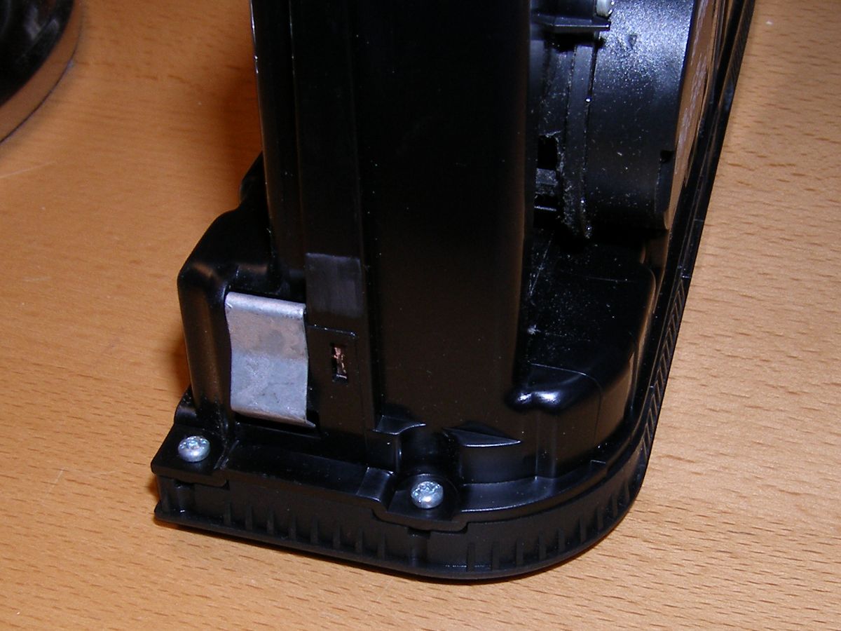 Removal of the faceplate requires, among other steps, removal of these two Torx T7 screws on either side of the case. |
 To free the top of the faceplate, press down on the small tab in the center of the faceplate as depicted here. |
 The bottom of the faceplate is freed by squeezing the two hook-like latches and then pushing both hooks toward the front of the case. |
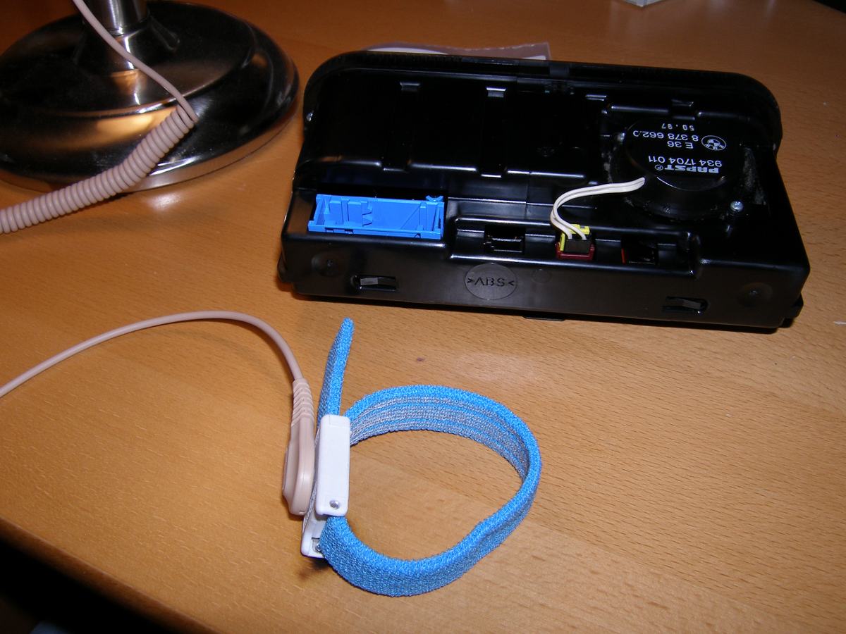 Always use a wrist strap when working with electronic components. This is especially important in low humidity conditions (like winter). |
 This is what my fan looked like after being in service seven years. |
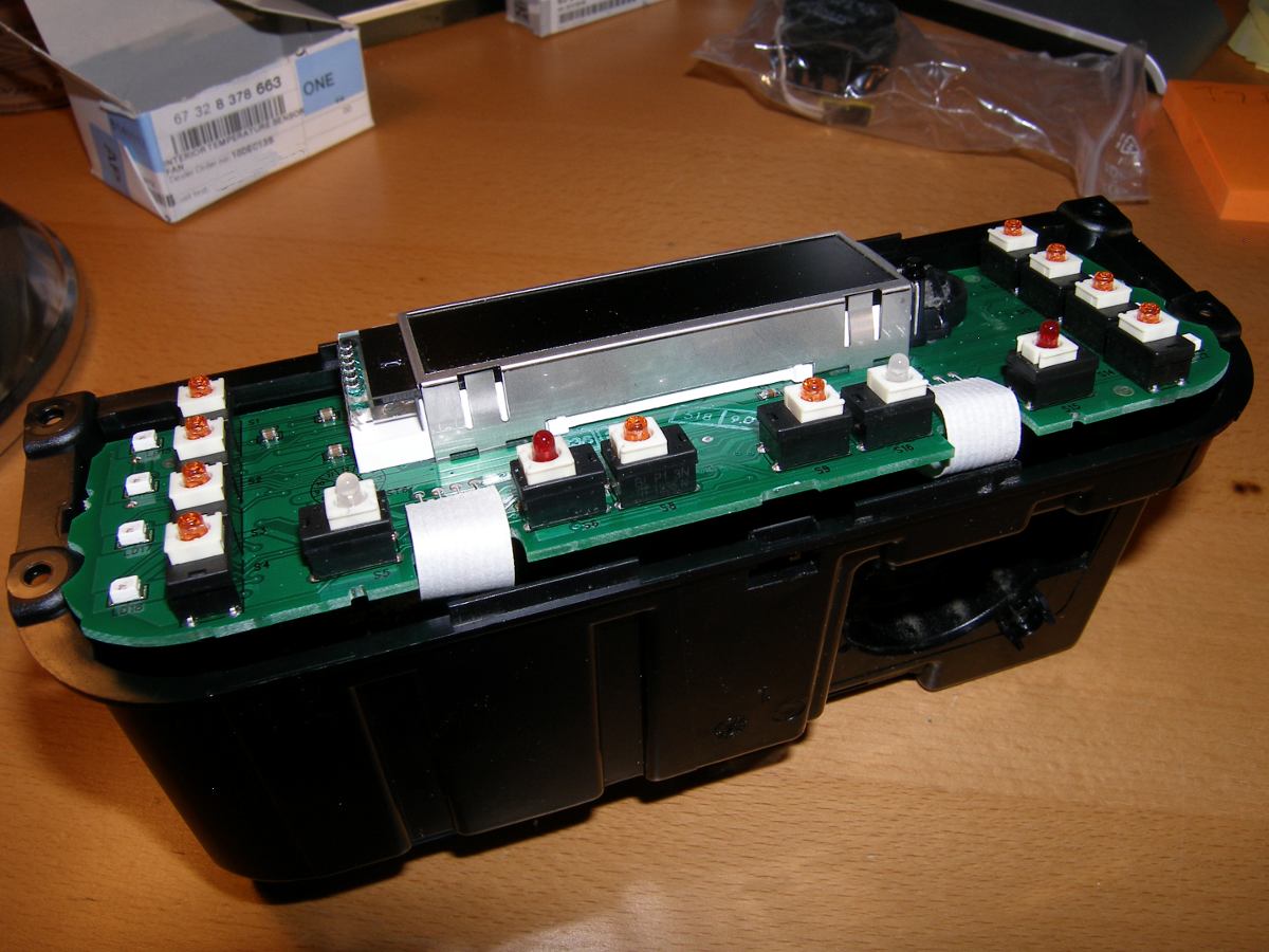 Once the faceplate and fan are removed, it's time to unlatch the front logic board. |
 The logic board is connected to the rear board with some ribbon cables, which allow the board to be pivoted down to gain access to the rear logic board. |
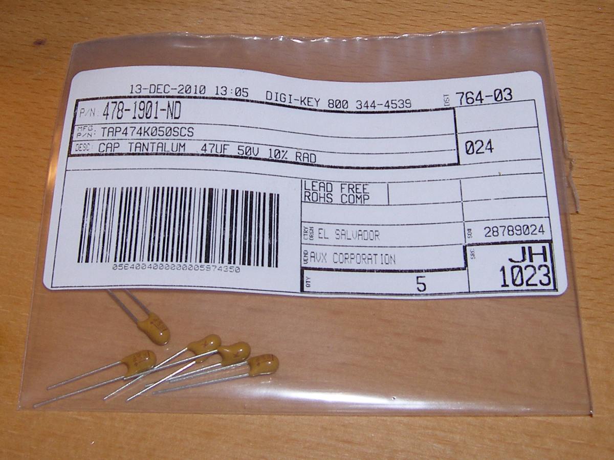 I bought a bag of five AVX TAP474K050SCS 0.47 microfarad 50V 10% tolerance capacitors. This should cover another four repairs or about 24 years of service. :) |
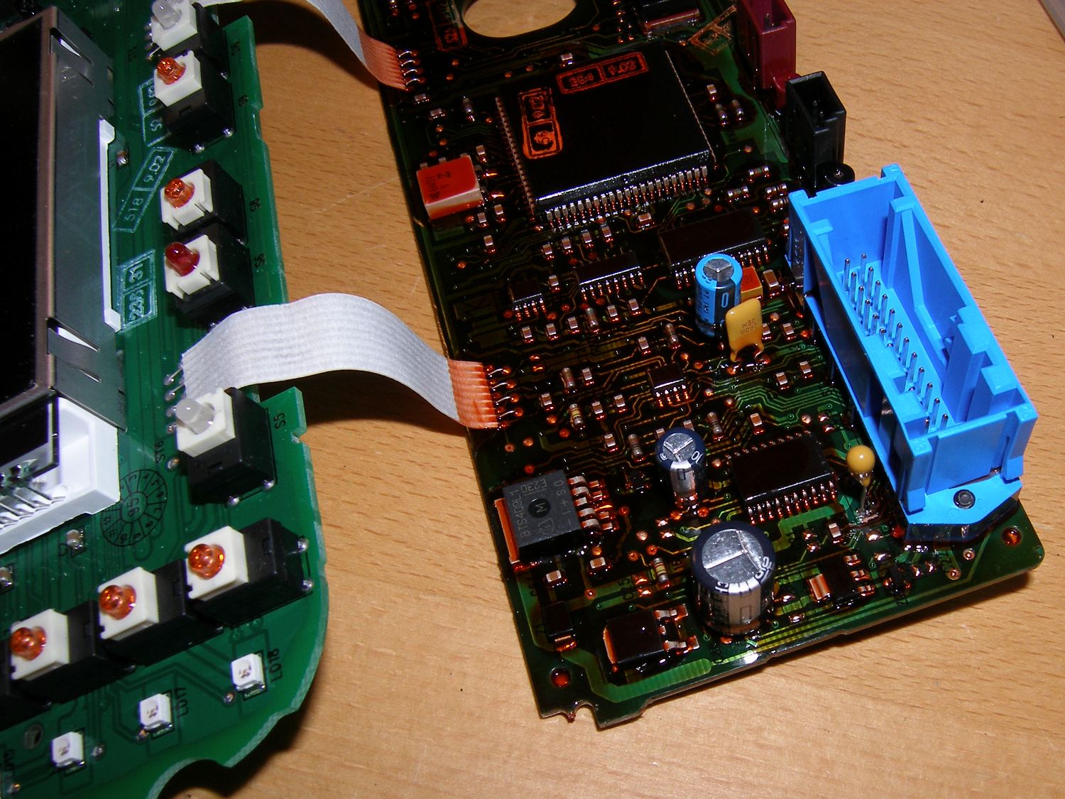 Just a top down orientation shot. You can see the logic board traces clearly here, which is what I used to determine the correct polarity. |
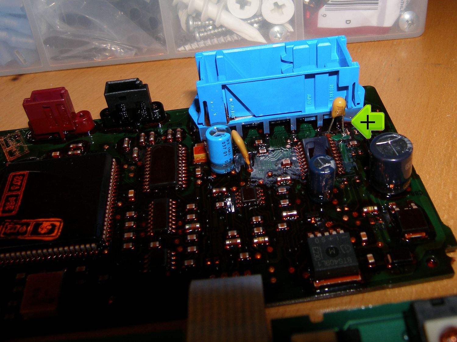 This shot shows the new capacitor installed with a pointer to the positive lead, which is identified on this part with a + symbol and a line pointing to it. |
 My original fan did not use the spacers but the new fan I received included some spacers, probably because this fan is used in other applications. |
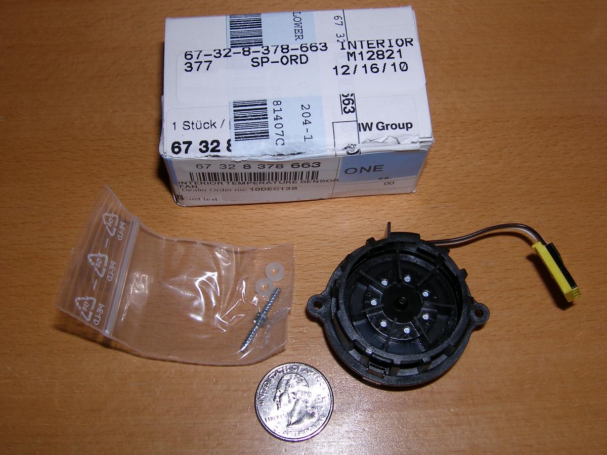 Just a closeup of the new fan part with part number. Good for another 13 years of service. |
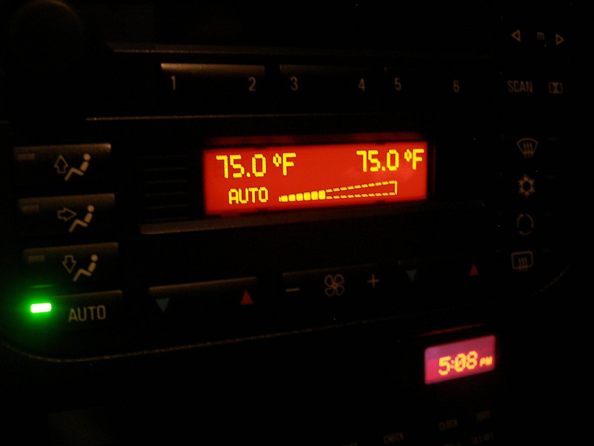 The downside to doing work in the winter is when you finish at 5PM, it's pitch dark. The upside is I got to enjoy the rich (and continuous) display backlighting. |
Conclusion
DIY component level repair is becoming increasingly difficult given the pervasive use of large scale integration (LSI) and surface mount devices (SMD) in modern electronic designs. Developed in 1995, the E36 HVAC controller leverages SMD, but fortunately the part that fails is mounted using conventional through-hole technology. Therefore, anyone with a simple soldering iron, desoldering bulb, and the skills to use them should be able to replace the capacitor.
The entire process took about 1 hour, with a good five minutes of that time spent trying to figure out how to remove the rear logic board without damaging it. In retrospect I should have used a vice as a "third hand", but I did manage to do the job without one.
For those who are bound to ask, I have no interest in fixing HVAC controllers as a service. If you are not equipped to do this repair you have a couple options.
Option 1: If you can at least protect your working environment from ESD and want to disassemble the unit, you can take the logic board and capacitor to a local electronics rework shop. An experienced professional equipped with a desoldering station will make very quick work of this. Prices vary for this service, so be sure to negotiate that up front.
Option 2: Send the entire controller to someone who advertises HVAC controller repair. There is at least one company I found online that will do the work for $50 plus shipping. Note, however, that I have no personal knowledge of this company, have not communicated with them in any way and therefore do not endorse their work. Let your fingers do the Googling and, as usual, caveat emptor!