


Amp Camp Amp (ACA) Project
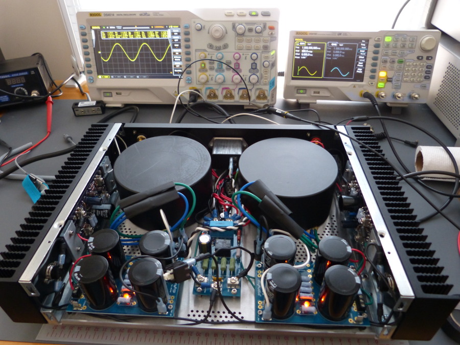
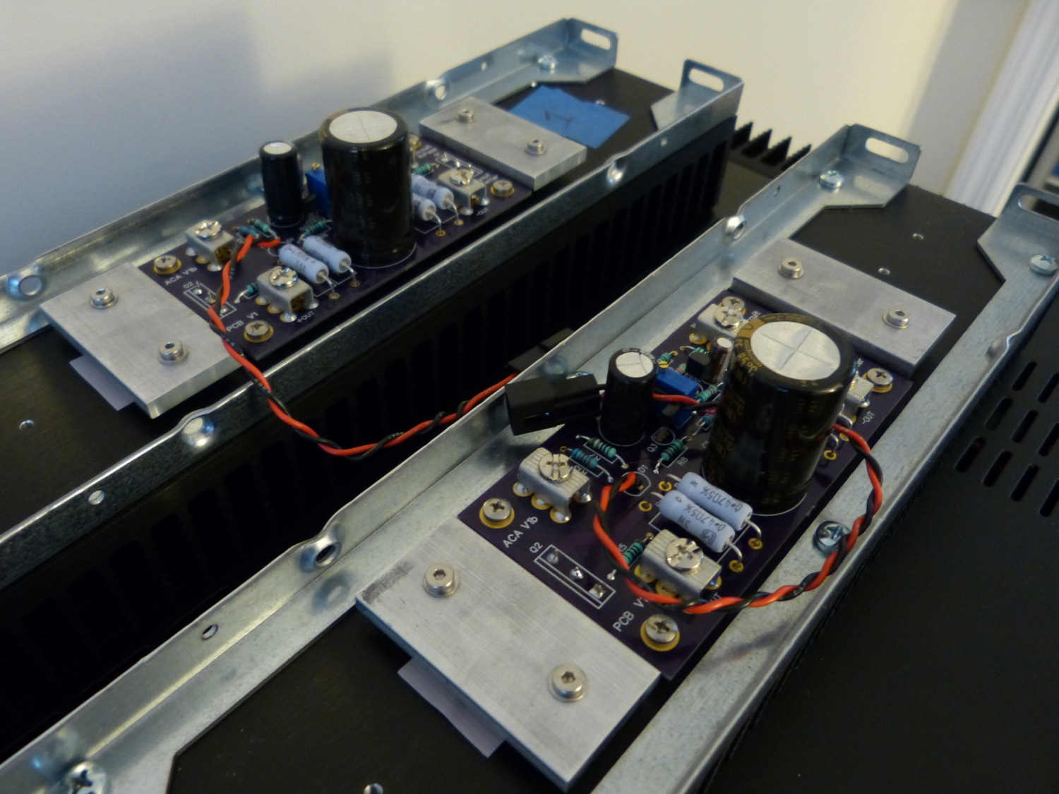
My Nelson Pass Amp Camp Amp on the bench during initial signal
tests.
Introduction
This article details the design process for the chassis and linear power supply I built to support the Nelson Pass Amp Camp Amp (ACA) Class A audio amplifier. I also built a custom PCB with Diptrace for this amplifier to accommodate my chassis design and you can read about that in my ACA PCB article.
Chassis and Heatsink Selection
The original Amp Camp Amp was implemented in a custom monoblock chassis manufactured by diyaudio.com powered by an off-the-shelf external switch-mode power supply (SMPS) capable of delivering 19 volts and up to 2 amps. The diyaudio ACA chassis is relatively small and based on a 2U x 200 mm heatsink with 40mm fins. I determined early on that I did not want to deal with the unwieldy nature of monoblocks but wanted to preserve, to the extent possible, the benefits of individual power supplies. This caused me to consider a dual mono configuration, which is the term applied to two completely separate power supplies and amplifiers installed in the same chassis.
I could have bought one of diyaudio's other chassis to house the amp but I quickly ruled them out as they are designed for more powerful amplifiers with higher heat dissipation requirements and simply take up too much space. As I knew diyaudio's chassis were manufactured by ModuShop in Italy. I browsed their site and ultimately imported a couple of their Dissipante 2U x 300 mm units with 10mm front panels. These come with 80x300x40mm heatsinks that are dimensionally identical to the original diyaudio ACA chassis heatsinks with the exception of the width of the extrusion (the depth the chassis in this case). As it turned out several people who had built the ACA noted that the "stock" heatsinks grew quite hot to the touch so I knew upsizing would be a good idea. That made the decision easy. Before I clicked "buy" I also selected the optional front handles, since I knew this amp would be quite heavy when equipped with two transformers, and the optional rubber feet.
An aside: I should point out that while the heatsinks required by Class A amplifiers are usually quite huge, the good news is that they are relatively easy to size because the worst case dissipation for a Class A amplifier is idle or without a load connected. That means the temperature of the heatsink, and ultimately the die temperature of the output devices, is maximum at idle. Once you connect a load (speaker) and start cranking up the music more current is diverted to the load rather than dissipated in the heatsink. So that means the running temperature of a Class A amplifier heatsink will actually drop with usage and then eventually return to the maximum once music stops.
The dirty little secret in the commercial amplifier world is that your typical Class AB amp will actually go into protection mode (shutdown) if driven sufficiently hard for a long enough period of time. This is because the designers are forced to make compromises in the size of the heatsink to save cost. There has been some industry standardization with respect to the duty cycle amplifiers should be designed to handle without shutdown but next time you buy a Class AB amp that you think is a steal look at the size of the heatsinks and then consider for a moment if the amp will actually generate its rated power for the duty cycle you require without shutting down, or worse, burning up. Fortunately we in the DIY world are not subject to the same cost constraints and can build an amp that will run continuously at rated power, as the ACA will do on either the original (200x40mm) or 2U chassis (300x40mm) heatsinks.
Supporting Feet
The ModuShop feet suck. Don't buy them. I found they were constructed of some plastic cups fusion welded to rubber -- hardly a resilient design. All of the cups moved a lot in relation to the rubber and one in fact broke free as I was playing with it, rendering it useless. As I knew the amp would be heavy and would very likely place significant side loads on the feet while moving it in the rack I quickly realized that I'd need to replace the factory units and settled on some feet manufactured by MNPC Tech I'd researched for an earlier project.
While the MNPC feet were intended to support PCs and at $40 a set of four they weren't exactly cheap I knew they'd get the job done. They were also higher than the ModuShop feet and I knew that would help raise the base of the chassis a bit and promote airflow circulation through the heatsinks -- a critical issue for passively-cooled designs like this one.
I also discovered that, presumably in order to reduce production costs, the top and bottom covers of the 2U chassis are identical parts. While the heatsink brackets are pre-punched to accept the mounting hardware of the feet the bottom cover is not. I ultimately decided to attach the MNPC feet to the base rather than through the heatsink brackets so I didn't need to worry about this.
Front Handles
The optional front panel handles consist of a hollow thin aluminum tube and a couple pieces of thick plate aluminum. I found the quality of the finish reasonable but the design is not without its flaws. While not obvious from the pictures on their site, the tube sits freely between the plates and the only thing retaining it are small recesses milled into the plates. My concern is that should the plates not remain parallel to each other under stress the tube could pull out and cause me to drop the amp. Handles responsible for holding 40+ pounds need to be reliable. These aren't in my opinion. That said, they look good and are worth the money because I couldn't build better pieces for less.
Incidentally, I discovered that the front panels are also not pre-drilled to accept the mounting hardware associated with the optional front handles, but they did mill out the rear face of the front panel in the locations where drilling is required and went to the extra effort to mill a smaller recess within a larger one so as to help locate the drill bit.
New Baseplate Design
With the chassis in hand I found the top, bottom, and rear panels made of a relatively thin 18 gauge steel. I was not pleased when I saw the chassis bottom plate bowing noticeably while test fitting the heavy transformers. While the rigidity of the part improved when I mated it with the heatsinks the base plate still bowed too much for my liking, and this isn't just a cosmetic issue.
 Despite the fact that toroidal
transformers tend to contain much of their alternating magnetic
field, if you can't locate all the AC components in a separate or
perfectly shielded area within the chassis, steel shields are
always a good idea in audio applications. The shields in this
case are constructed of a large center post and cover designed to
almost fully enclose the torroid. The key word is ALMOST, as the
center post is in fact slightly taller than height of the
material that encloses the torroid. What results is a very small
gap around the outer base of the shield, and this gap can never
close (meaning, the outer edge of the shield cannot come into
contact with the baseplate) or a shorted turn will result. Google
shorted turn transformer if you want to
know the details but suffice it to say a shorted turn would
render my transformers near worthless, so that drove the need to
replace the baseplate with something a bit more stout.
Despite the fact that toroidal
transformers tend to contain much of their alternating magnetic
field, if you can't locate all the AC components in a separate or
perfectly shielded area within the chassis, steel shields are
always a good idea in audio applications. The shields in this
case are constructed of a large center post and cover designed to
almost fully enclose the torroid. The key word is ALMOST, as the
center post is in fact slightly taller than height of the
material that encloses the torroid. What results is a very small
gap around the outer base of the shield, and this gap can never
close (meaning, the outer edge of the shield cannot come into
contact with the baseplate) or a shorted turn will result. Google
shorted turn transformer if you want to
know the details but suffice it to say a shorted turn would
render my transformers near worthless, so that drove the need to
replace the baseplate with something a bit more stout.
I have been working with Solidworks for over a year now on other projects and had already modeled the transformers and some other parts for a fully custom chassis so I decided to model the 2U chassis as needed to design a new chassis base out of 14 gauge cold rolled steel (1008) and have it manufactured in small quantity. The end result provides all the holes necessary to mount the transformers, the diyaudio soft start board, the diyaudio universal power supply CRC filter boards, Vishay 35A potted bridge rectifiers, the hardware associated with both the safety ground and star ground, and the MNPC chassis feet. I also added groups of 3mm ventilation holes in various locations that would not conflict with the mounting of the components, and wrapped it up with holes required to fasten the baseplate with the existing heatsink brackets.
If you're wondering why I selected 3mm holes and spaced them as such, that is based on research that revealed this hole pattern blocks somewhere north of 99% of all RF radiation below 6 Ghz. The elongated ventilation holes used on the stock panels are somewhat less effective at shielding high frequencies (think WiFi @ 2.4 or 5Ghz) but I wasn't about to spend money replacing the top panel for a DIY project. I figured the factory piece would be good enough.
While my custom plate doesn't look like much it saved me an incredible amount of work and frustration. I'll let you in on a hard lesson I learned while constructing this amp. It looks easy enough to gather the tools and drill a few holes in a piece of metal...and it is, provided the locations of the holes are not particularly critical. For example, it doesn't really matter if the Vishay rectifiers are a 1mm this or that way. Center punch, drill, debur, and you're done.
Drilling holes to support a PCB with 4+ mounting holes, all of which have maybe 0.5 or 1mm clearance, is another story entirely. In fact, I spent the better part of one Saturday afternoon attempting to drill a measily eight holes in two heatsinks, wound up breaking two bits and never did get the holes aligned sufficiently to allow mounting of the PCBs without the screws trying to cross thread in the standoffs. I was forced to give up, relegate those heatsinks to another duty (transistor matching if you must know) and order another set from ModuShop to have them CNC drilled and tapped. Now you know why I developed the baseplate in CAD and had it professionally manufactured. I wasn't about to repeat that mistake.
Mains Inlet
One of the earliest amp designs I worked on included a discrete IEC mains inlet, switch, fuse holder and EMI filter components. I think the parts were somewhere in the neighborhood of $10. What I didn't realize at the time was that, despite being somewhat more expensive at around $22, an IEC mains connector integrating all of these components would be the smarter choice for several reasons:
If the IEC cord connector and switch are separate mains voltage will always be present in the chassis when the power cord is connected, regardless of the position of the switch.
It's also necessary for safety reasons to protect the switch with the fuse, so the power must be wired from the IEC inlet to the fuse and then to the switch. Easy enough to get it right, but equally easy to screw up, particularly if you lack experience working with mains voltage. Do it the wrong way and a short in the switch will cause sparks until the branch circuit breaker trips.
It's really important to correctly implement an EMI filter. Not only are the correct high voltage X-type capacitors required, it's essential that this filter be implemented as close as possible to the location the mains voltage enters the chassis to minimize radiation within the chassis. It's almost impossible to achieve optimum results with discrete components for this reason.
So for this project I shelved the discrete components and bought a Schurter mains inlet that contains the IEC cord entry point, 10A mains rated switch, two pole fuse block (taking 5x20mm glass fuses) and an EMI filter...all within a nicely shielded formed aluminum case. The perk? It takes a lot less space in the chassis. I'm all for discrete components, particularly if there is something to be learned with their use, but I think the DIY crowd is best served by using an integrated connector because it improves safety and EMI compliance.
Transformer Selection
Although many ACAs have been built using the specified SMPS some advanced builders noted better dynamics particularly at lower frequencies when paired with a linear supply so that in combination with my prior experience in building them convinced me to build one for this application.
While Class A amplifiers typically place harsh demands on the power supply those demands are largely a constant. So to size the power supply all you have to do is figure out the current requirements at idle and you're done. This is due to the fact that the output transistors of a Class A amp are conducting continuously and typically use a fixed bias, drawing the same amount of current all the time, regardless of the state of the input signal.
Nelson indicated in the ACA document that the circuit draws about an amp at 19 volts per channel. That means the board requires a supply capable of providing 19VA at a minimum. As I discovered, however, Nelson's power estimate was a bit optimistic. My custom PCBs, when connected to a bench supply with current shunts, showed a constant draw of 1.38 amps (about 26 watts). That means 1.38A * 19V = 26VA is required. Nelson has also indicated in other design discussions that barring cost or other constraints he suggests tripling that number to arrive at the optimum transformer size, or in this case, 26 * 3 = 78 VA.
I wound up using an Antek 200VA 15V unit because I had it in stock. Normally over-engineering like this comes with some compromises but with transformers used for audio amplifier power supply applications bigger is almost always better. The only downsides are physical dimensions (will it fit in the chassis?), weight, and cost. My 2U chassis fit my oversize transformers adequately, if not comfortably, and I found the cost increase relative to a 100VA unit to be minimal (effectively irrelevant for a one-off DIY design).
One of the perks of using an oversized transformer, particularly in an unregulated supply such as this, is an assurance that the supply voltage will not drop as much with an increasing load. In my case the 200VA transformer can supply more than enough current so while the voltage in each supply does decrease from 20.3 volts unloaded to exactly 19.0 volts with the board connected, the only detrimental effect of this loading is actually an increase in ripple, which goes from unmeasurable with my instrumentation to roughly 55mV peak (110mV p/p). That is more a factor of the capacitance used in the filtering section than the transformer size.
I should note that the transformers I used were equipped with dual primaries and secondaries. Dual primaries can be wired in parallel or series to adapt to different mains voltages (120 vs. 240VAC) while the dual secondaries can also be wired in parallel to provide a single power supply or used independently to create two separate power supplies with each supply providing half of the current rating of the transformer (200VA / 2 = 100VA in my case).
While I ultimately decided to use two transformers and wire the secondaries in parallel to provide the full 200 VA to each channel this was not necessary because 100VA is already four times that required. If you're looking for a technical reason why I chose to use two transformers I'm afraid you won't find it, but if an excuse will do it's that the shield provided by Antek for their 100VA and 200VA units is the same, so while the transformer itself might have been physically smaller the shields would have taken up the same space in the chassis.
I should also point out that my transformer manufacturer, Antek, also sells what they call a "shielded" transformer. These shields are not external shields but rather a static shield that is placed between the primary and secondary to improve isolation. I originally ordered the shielded versions because the cost increase was minimal but unfortunately Antek shipped me the unshielded versions and it was just easier for them to credit me the very small difference in price so that's what we did. I actually have plans to build a second ACA in the same chassis and expect to buy the shielded versions simply to see if there is any noticeable (i.e. audible) difference. [Edit: There isn't any difference from what I could tell].
Rectification and Filtering
While the universal supply PCB comes with rectifier boards their design requires expensive discrete diodes and heatsinks for each diode, none of which is strictly necessary for an amplifier the size of the ACA. This explains why I set those boards aside and specified some dirt cheap and effective 35A Vishay bridge rectifiers. The rectifiers don't technically require a heatsink at such a low current but I nevertheless attached them to the custom baseplate and located them between the transformer output and the filter input in an attempt to keep the associated wiring as short as possible.
I originally planned to use a CLC filter with this amp because CLC filters actually produce ripple approximating a sine wave while CRC filters like the ones I ultimately installed produce something closer to a triangle wave. Triangle waves unfortunately contain harmonics in addition to the fundamental frequency of two times the mains line frequency (60Hz*2 or 120Hz). See the oscilloscope screenshot.

The diyaudio unversal supply board indeed flexible but clearly designed for a bipolar supply (meaning, a supply that provides negative and positive voltage rails like +/-19V) As the ACA does not require a bipolar supply and I had already stuffed the boards I had to ignore the silkscreen and reverse the input and output polarity of the board that would normally be used for the negative supply to produce the desired positive voltage. So that's why you may notice the +19V terminal on the left channel PCB is connected to the terminal strip on the filter marked "GND". And it works just fine like this, though it does offend my OCD.
Soft Start
The downside of using good sized transformers and 60000 μF of capacitance per channel is the large inrush current that results in the first half second or so after the power switch is turned on. Some of this current is consumed by the transformer as the magnetic field develops. This is known as the magnetizing current. Once a voltage across the secondary exceeds the forward voltage of the rectifier diodes (about 0.6V) a voltage is presented across the filter capacitors, which then charges them. This is where a bulk of the inrush current is consumed.
Nelson Pass typically specifies a CL60 thermistor (a negative temperature coefficient or NTC resistor) to tame the inrush current in his DIY designs. When an amplifier power supply containing a CL60 boots up cold the device has a roughly 10 Ω resistance which slows the inrush current and prevents blowing fuses (either the amp's own fuse or the mains branch circuit supplying it).
The problem with these devices is that they remain in series with the mains current at all times, heat up to astoundingly high temperatures (150C+!) and still have some residual resistance when fully hot (which is the reason they get hot, incidentally). This resistance does not return to normal until the thermistor cools to near room temperature and this means thermistors provide no inrush protection during a "warm" reboot of the amp.
The diyaudio soft start board works around this by replacing the thermistor with a simple circuit that inserts resistance in the mains circuit by default, charges a capacitor when power is applied, and then energizes a relay to remove the resistors from the circuit. When the amp is turned off the capacitor discharges, the relay opens and the resistors are once again placed in the mains circuit, ready to accept another startup sequence. Simple and elegant.
My NAD 2200 amplifier has a large transformer and only 40000 μF of filter capacitance. When I turn that unit on it momentarily dims my lab lights and activates my UPS as the mains voltage dips in response to the short term load. I don't have a real power analyzer but I do have a Kill-A-Watt, and when I boot up the ACA I've noticed the total current does not exceed 0.76A @ 110V at any time, while the running load is 0.65A. The sample rate of the Kill-A-Watt isn't particularly high so the actual peak might be higher but the proof is in the pudding, as they say; my lights don't dim and my UPS doesn't go into protection.
Adding the soft-start circuit was one of the smarter design decisions and I sincerely doubt I'll build another amp without one. If you follow in my footsteps I suggest you integrate one as well. Incidentally, the diyaudio soft start board integrates a low value X-type capacitor (the blue box-like component) designed primarily to eliminate arcing in the mains switch.
Power Switch and Thermal Protection
While I could have used the switch integrated with the mains inlet on the rear panel as the only disconnect I decided to mount a Bulgin 10A mains-rated switch on the front panel for a couple reasons.
- Convenience. I argued that if I ever needed to shut the amp down quickly it would be far easier to access the front panel than the rear.
- Integration with the soft start board. The soft start board was designed to accept a mains rated switch and the board itself was ultimately positioned in the only place I could find for it -- near the front center of the chassis...or in other words, within a couple of inches of the proposed location for the front panel switch.
I decided to add thermal protection to the amp in the form of two mains-rated normally closed thermostatic switches, one mounted to each heatsink. I felt this was appropriate because the amps are in no way connected and one could be overheating due to a fault while the other was singing happily away. I therefore wired both thermostatic switches in series with the front panel switch, so if either heatsink exceeds 70C the power supply will behave as if I simply turned the front panel switch off and disconnect power to both channels.
In retrospect testing revealed heatsink temperatures no higher than 42C, so the 70C rating is probably a bit too high, but I decided to use them because I had them in stock for another amp project. I also wanted to reserve the opportunity to experiment and increase bias at some point, which will no doubt increase the steady-state temperature of the heatsink.
LED Indicators
 I knew from the beginning that I
wanted some kind of power indicator on the front panel. After I
settled on a dual mono power supply I realized that it would make
more sense to have two indicators.
I knew from the beginning that I
wanted some kind of power indicator on the front panel. After I
settled on a dual mono power supply I realized that it would make
more sense to have two indicators.
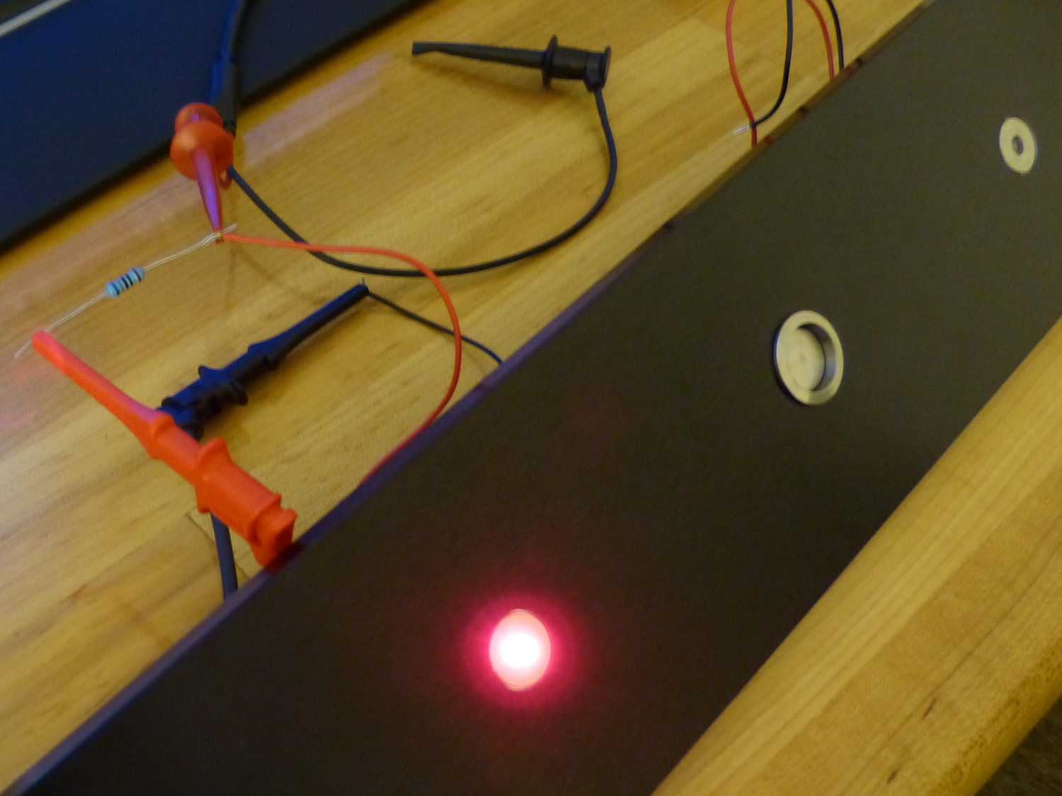
My original vision for these indicators was a diffused lens mounted flush with the front panel surface to give it a polished, professional appearance. The problem was everything I could find that was reasonably priced was actually designed to sit proud of the panel. After a couple hours of searching I finally came across a tamper proof LED manufactured by Bulgin and originally designed for kiosks. While the price was ridiculous I bought it primarily because it matched the same nickel finish and character of the front panel mains switch manufactured by Schurter.
In future projects I'll probably use a light pipe for several reasons:
- Cost. The light pipe assembly I bought for testing (after the panel had been machined) turned out to be about 25% of the price of the Bulgin indicator.
- Simplfied machining. I had to not only machine a large hole in the front panel to accept the indicator body but a small recess area as well to get the unit to sit flush with the face of the panel. That extra machining step may not seem like much but every second of CNC machining time translates into increased cost.
- EMI. The LED of the light pipe assembly is inserted directly into the PCB and this eliminates the flying wires associated with the Bulgin indicator. As any RF specialist will tell you every wire (and PCB trace for that matter) can serve as an effective antenna at some frequency, so the fewer flying wires on the PCB the better.
Incidentally, the current limiting resistor specified in Nelson's schematic (10k) was not correct for the Bulgin application so I calculated my own value (680 Ω) based on the supply voltage (19V), forward voltage of the LED (2.2V for green and 1.85V for red with Bulgin's indicators) and current (25mA green, 30mA red). I found the red indicator to be almost offensively bright when run at the recommended current (30mA) so instead of using the lower nearest value of 560 Ω I specified 680). That value ran the LED at 25mA where the intensity was a lot more reasonable and I wasn't at risk of taking out incoming ICBMs. :)
Highlights
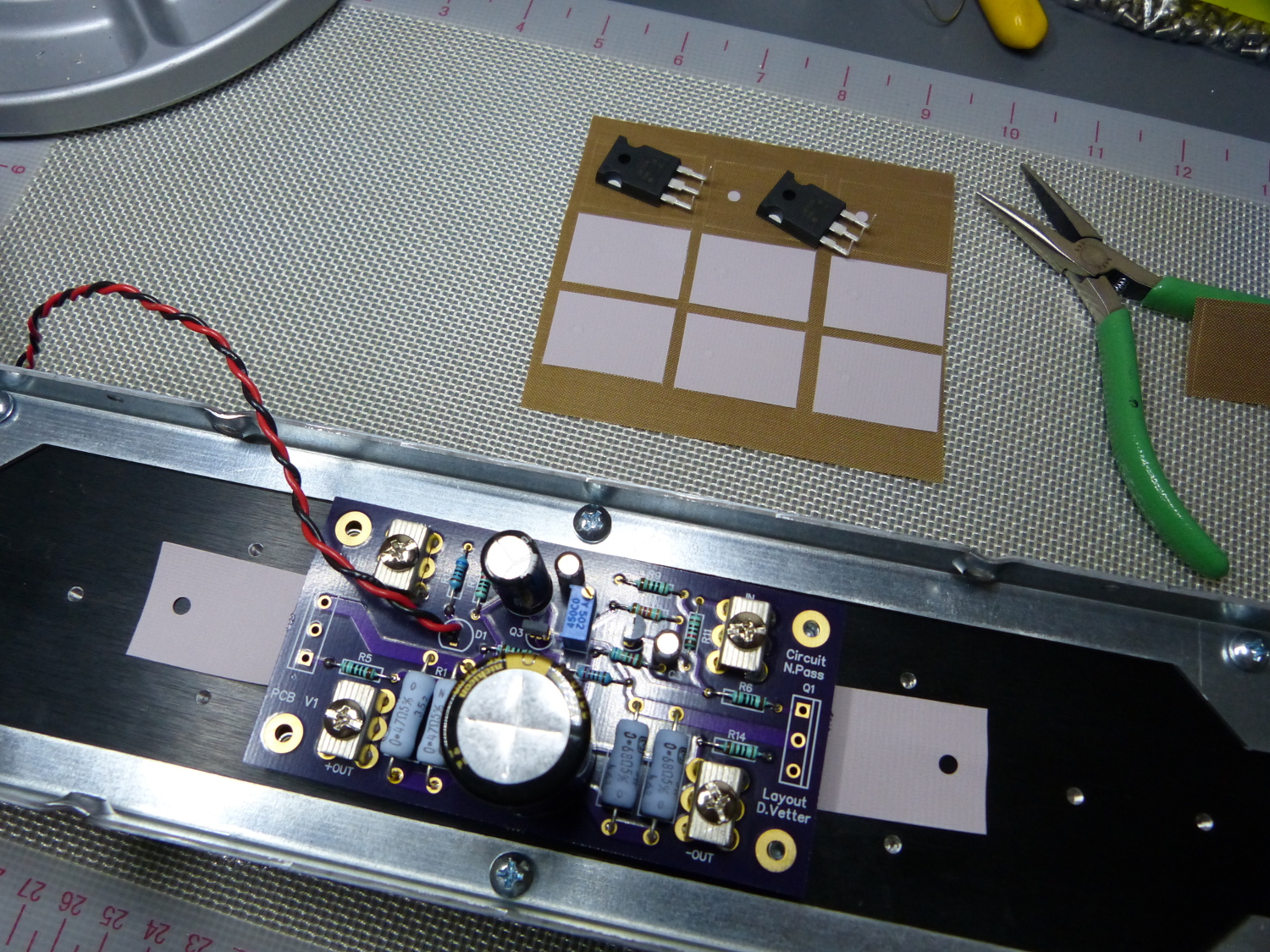
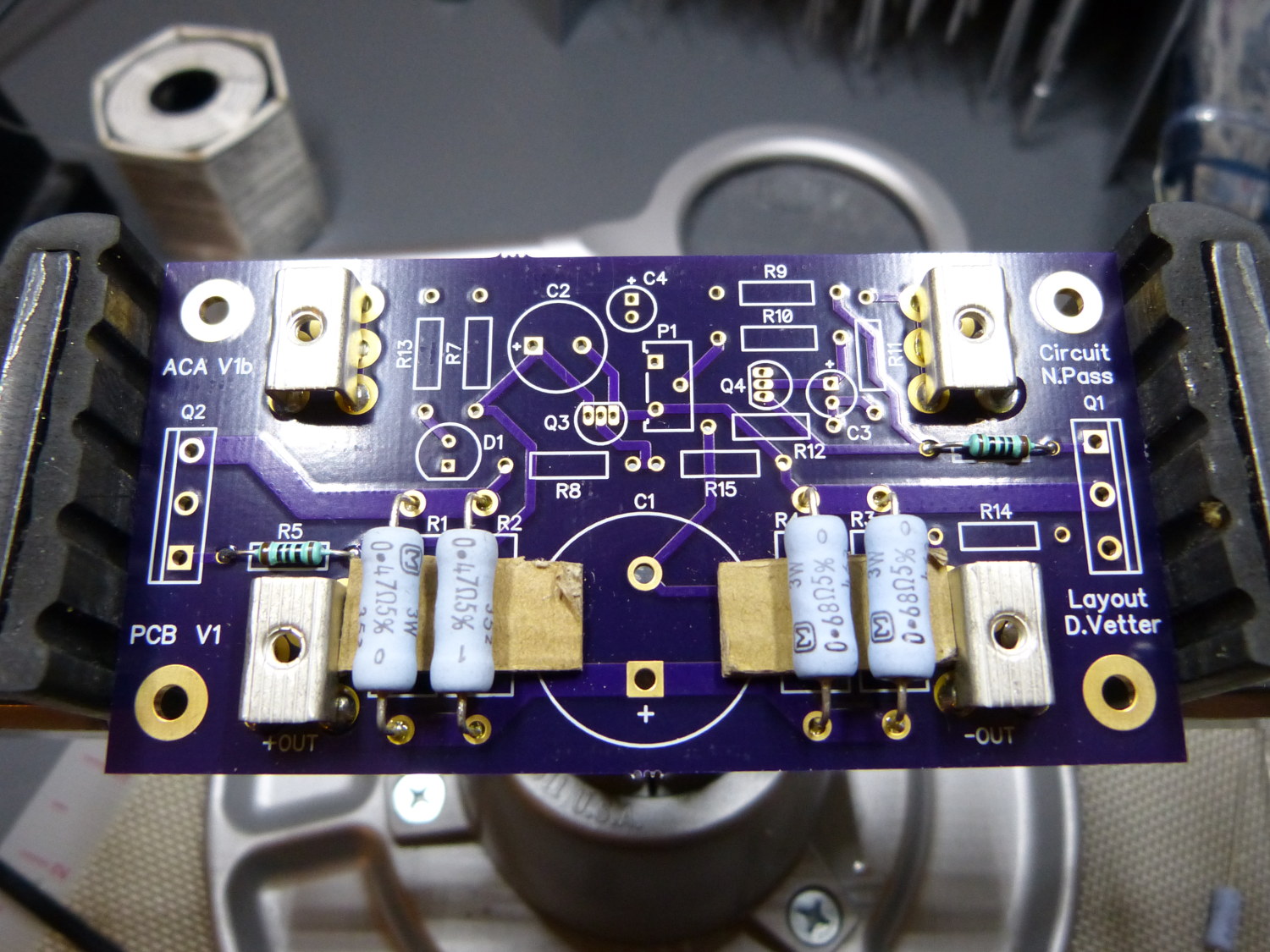 I use a piece of cardboard to help keep the high power resistors offset from the PCB. This helps air circulate around the devices. |
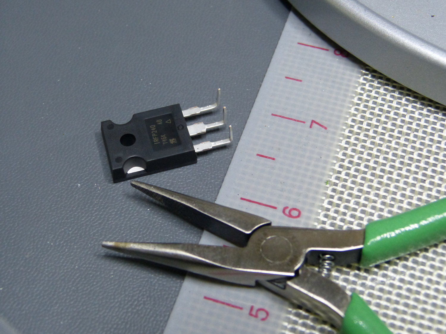 Because these FETs are mounted parallel to the PCB the leads must be bent 90 degrees. A longnose pliers works well here. |
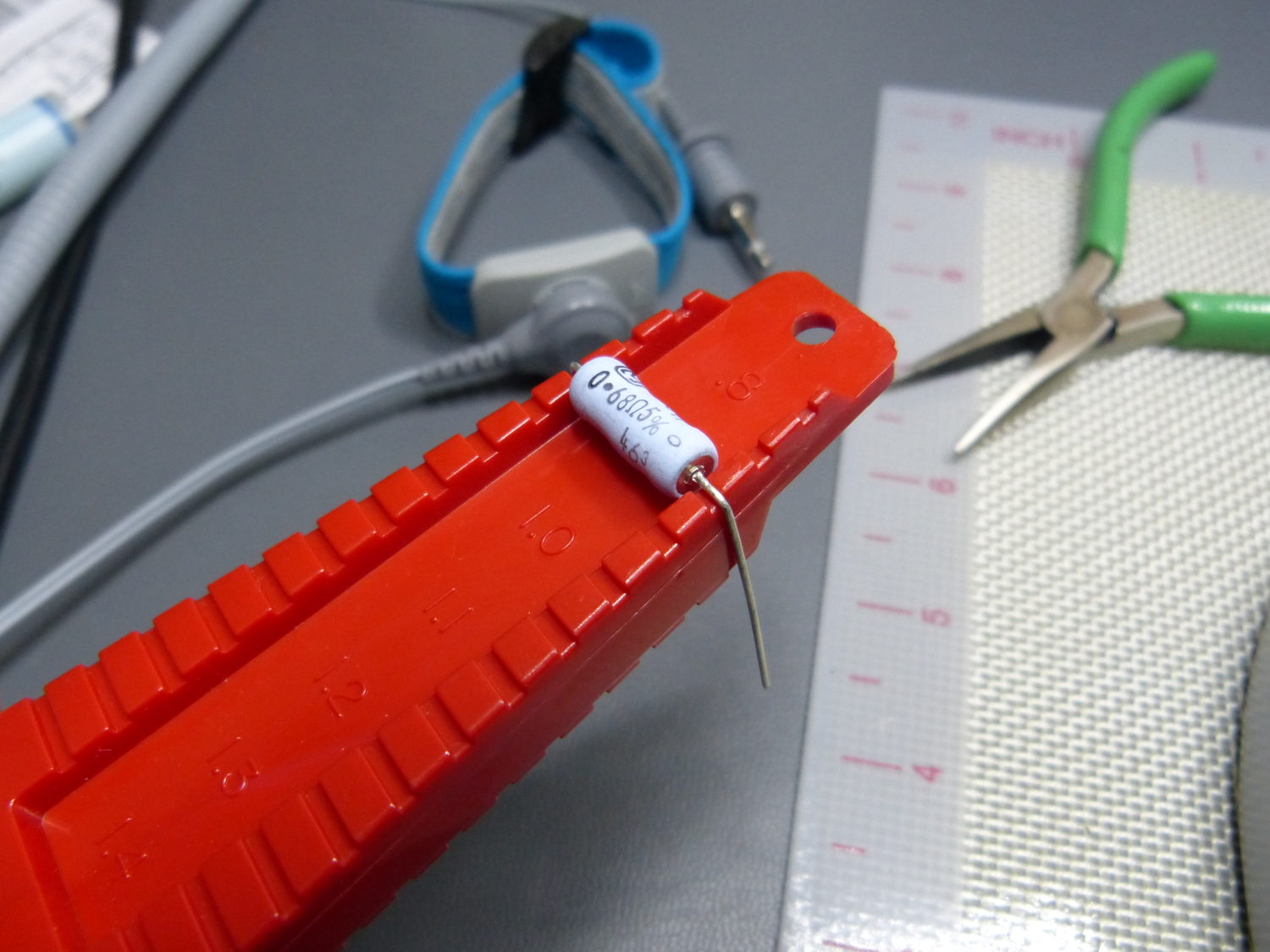 Hard to find these days, but quite handy, is this resistor lead bending tool. This makes it trivial to consistently produce sharp 90 degree bends with the correct lead spacing. |
 One of the PCBs I built for my second ACA chassis. Panasonic has discontinued the output cap in the original BOM so I splurged on a Nichicon Gold Tune to see if I could hear a difference. |
 The high thermal efficiency of Keratherm 86/82 can increase the lifespan of devices by reducing their junction temperature or it can permit the use of a smaller, less expensive heatsink, reducing overall project cost. |
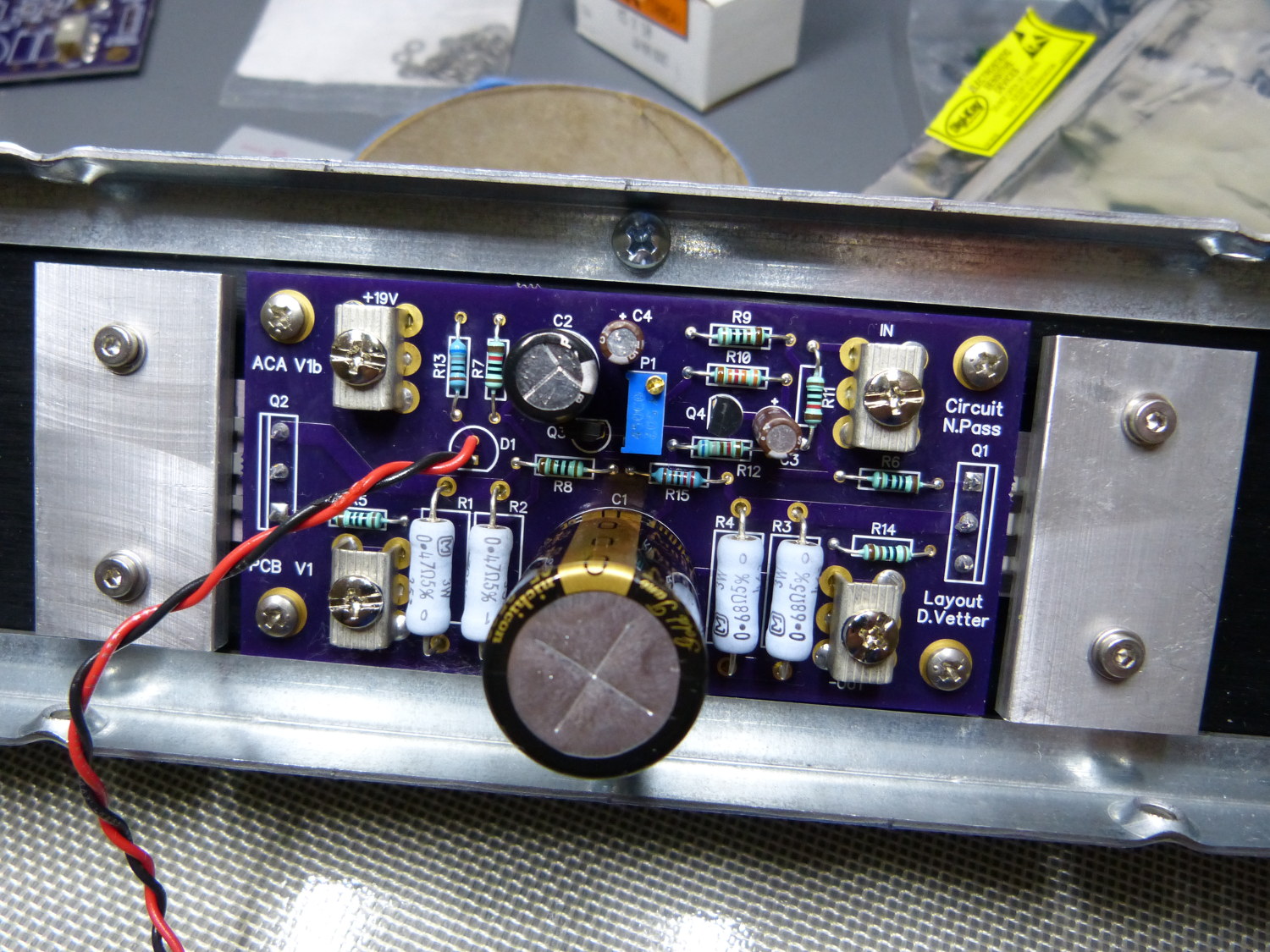 The finished PCB installed on the heatsink. I installed this once to solder the FETs from the top of the board and then pulled it to clean all the flux off the board before reinstalling it. |
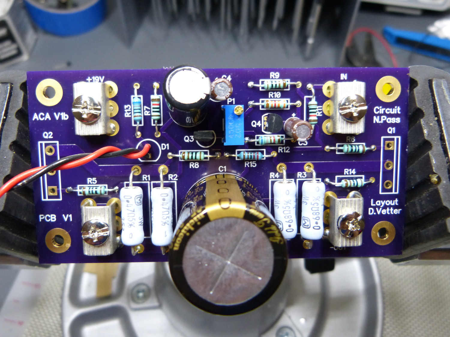
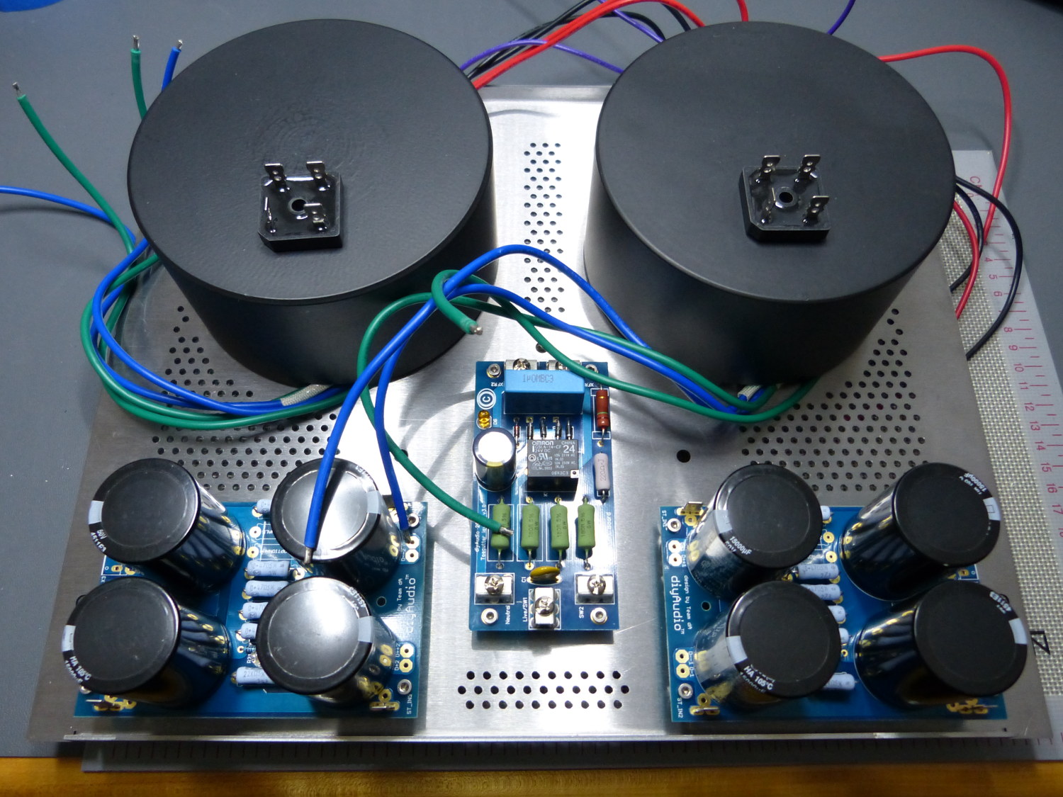 The second chassis and power supply build underway. I decided to install one of the three "optional" resistors to see what effect that would have on ripple. |
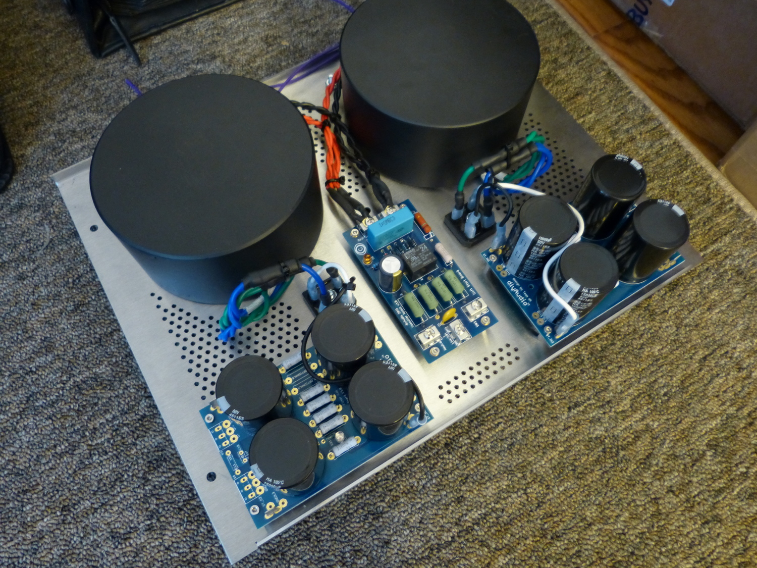 Almost ready for powerup. If you compare this to the pictures earlier in the article you can see I streamlined the transformer secondary wiring substantially. I hope this helps reduce noise. |
 The two amplifier channels finished, including pigtails for the front panel LED indicators. The black shell is one half of a keyed, mating pair from AMP. |
Conclusion
This project was primarily designed as an instructional tool and in that sense it was successful though it did cost a lot more than expected despite my use of many off-the-shelf components. Most of the cost was incurred in the production of the custom baseplate and CNC machining of the front and rear panels and heatsinks. Still, I built it without compromise and that should be the goal of all DIY designs.
After hours of testing the hottest temperature on the heatsinks is 110F and that occurs near the amplification device (Q1). The current source (Q2) runs nearly as hot, but is consistently a degree or so celcius cooler. I don't have temperature data from the original chassis but it's safe to say that the 300mm extrusions allow the amplifier to run considerably cooler and since heat is the enemy of all silicon devices deploying the ACA in the 300mm chassis should result in greater longevity.
So how does it sound? In a word, great, and not just because I built it. I was particularly impressed with its high frequency response which I found forward but smooth, and not at all harsh like several commercial amps I've heard. I must admit, however, that the amp is not dead silent. With my ear a couple inches away from the tweeter and no music playing I can hear a quiet buzzing sound that is caused either by the ripple on the rails (110 mV p/p) or a simple matter of coupling due to packaging. I knew the small chassis would result in some compromises including the placement of A/C wiring in close proximity to DC circuitry and small signal wiring so this is not exactly a surprise. However, refreshingly, there is no hum or hiss, which I believe validates my grounding scheme. Star grounds work.