


Saturday, June 23, 2012
Front Suspension Overhaul - Day 8
The bolts for the heat shield arrived promptly from McMaster-Carr so one night this week I drilled and tapped the right side engine support for the M8 button-head screws I used to attach the heat shield. Despite the cost of this little diversion I'm very happy with the end result. The video tells the full story.
I originally planned to begin work today by removing the steering column but I received a call from the powdercoater this morning indicating that the remaining parts were ready to pick up so I switched gears and ran over to his shop. Inspection of the parts revealed that he did a great job masking the kingpins so they now look better than new. Earlier in the week I asked him to make a point of getting powder (paint) inside the pockets we had reinforced on the subframe, simply to ensure I wouldn't have a rust problem in there, and he managed to address that nicely. He even took care to mask off a few of the areas on the brake caliper brackets I mentioned to him. Overall, everything came out as I expected. The original estimate for the work was $300 and the total came out to be $340, which I think is bargain considering I couldn't do the same work myself (factoring in my time) for less.
I left the powdercoater and ran over to the dealer to pick up the latest parts order including the new sport package swaybar (31351090182) and lower steering column parts including the lower metal bearing. Total bill this time: $175. Once at the garage I pulled out all the parts and instantly decided that installation of engine supports, mounts, heat shields, and subframe would be a lot more emotionally rewarding than screwing around with those damned fracture bolts. Can you blame me?
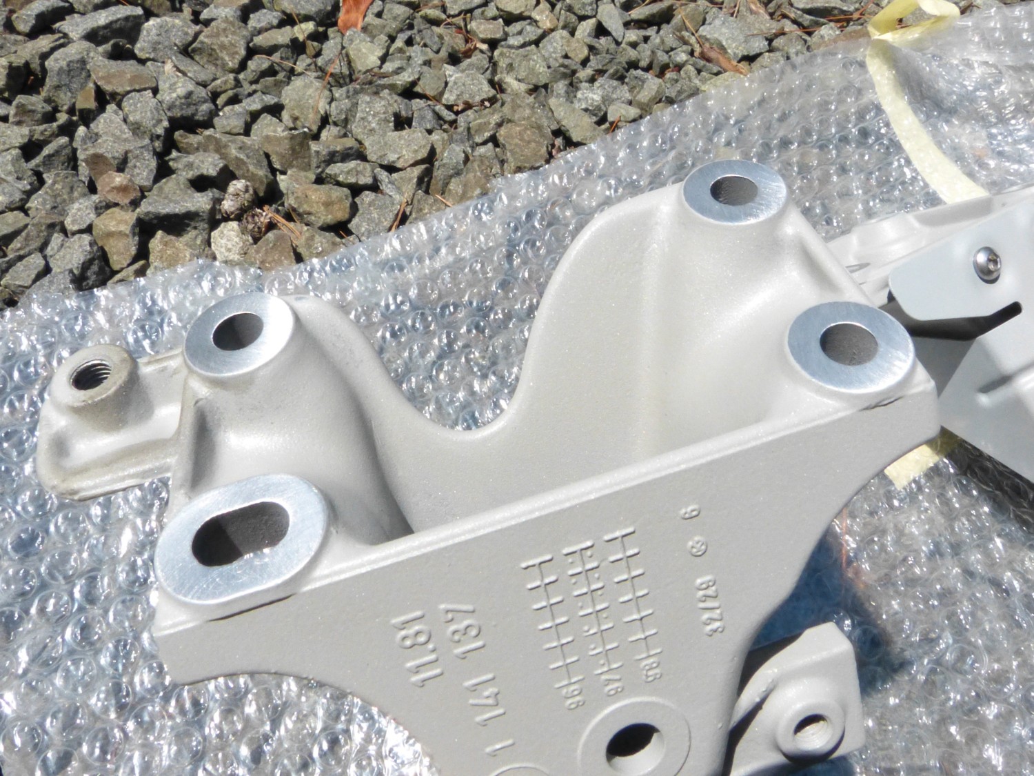
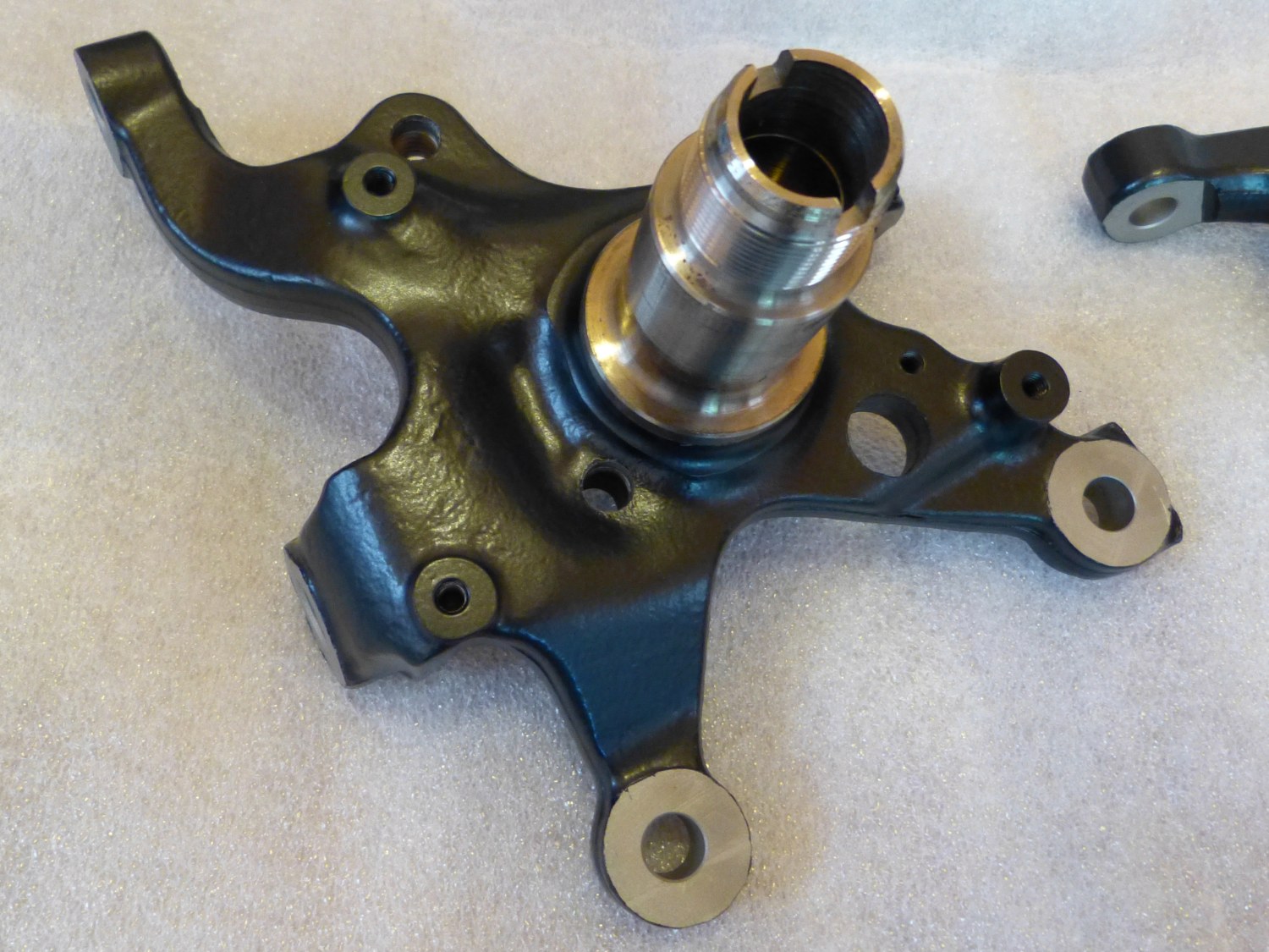 The appropriate areas of the kingpin were masked off and as a result it literally looks better than new. |
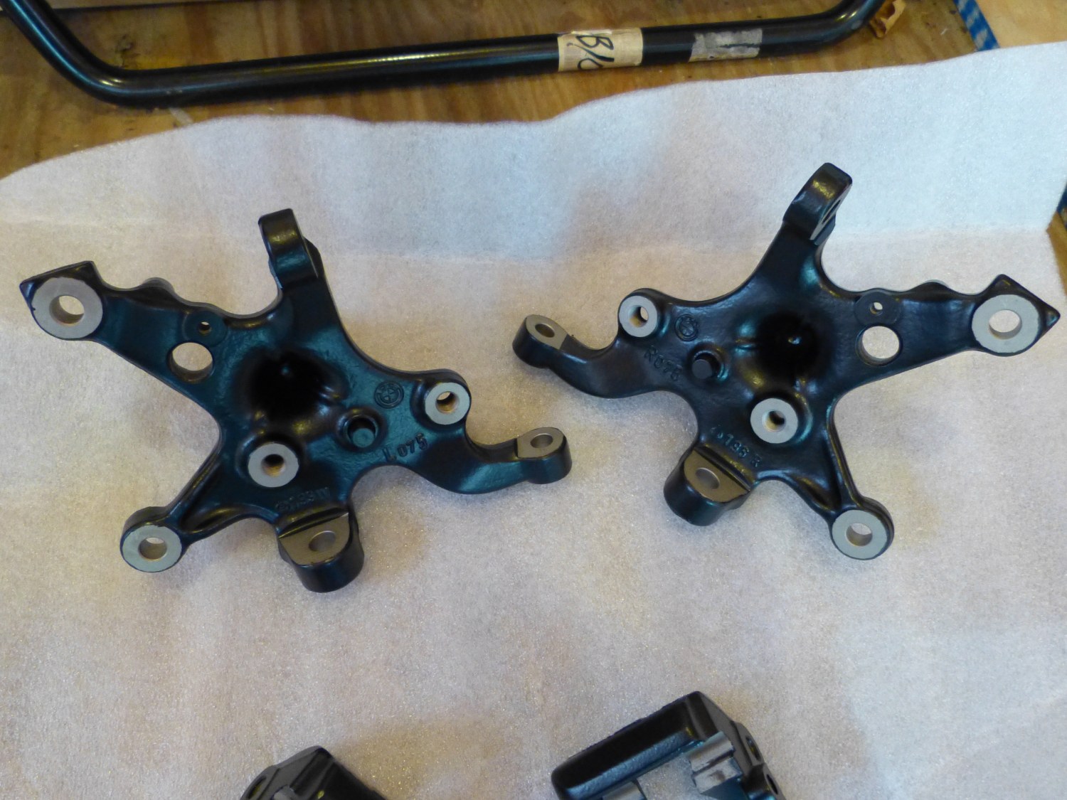 The rear of both kingpins. Was powdercoating these essential? Obviously not...but you can't argue with the results...they look better than they did. |
 Look ma, no more scratches on this factory new part. I'm really looking forward to installing this piece since it will mean the overhaul is complete. |
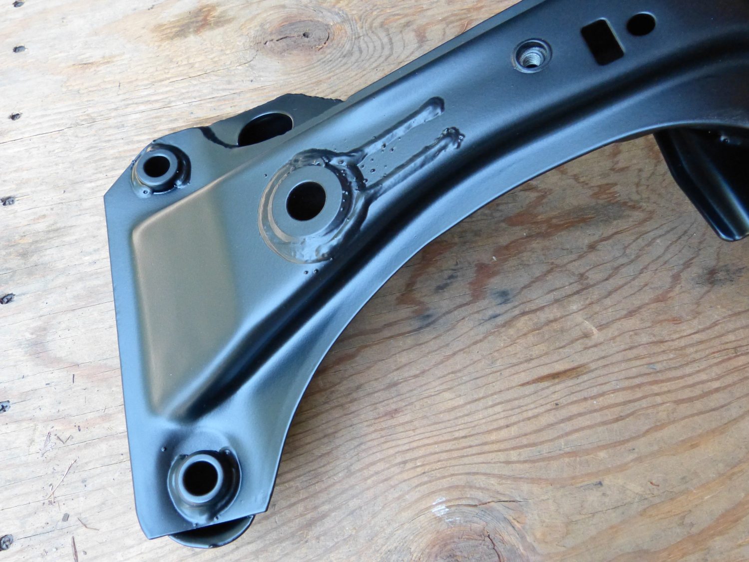 Closeup of the top right side of the freshly powdercoated subframe. Note how the nutsert is coated and sealed with paint. It looks like it came that way from the factory! |
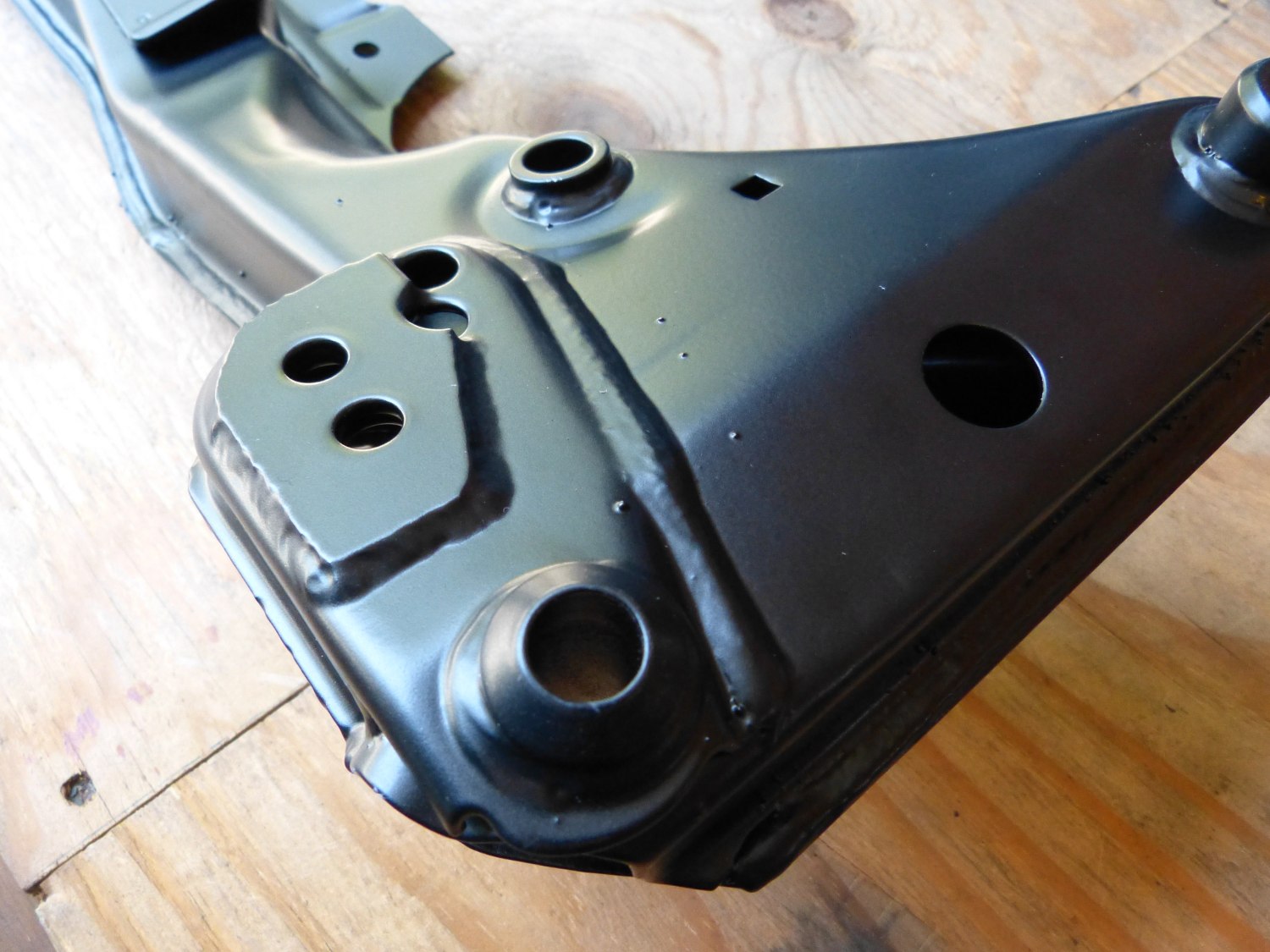 Another perspective of the upper reinforcement on the subframe. The thicker powdercoating process tends to smooth out the welds and make it look OE. |
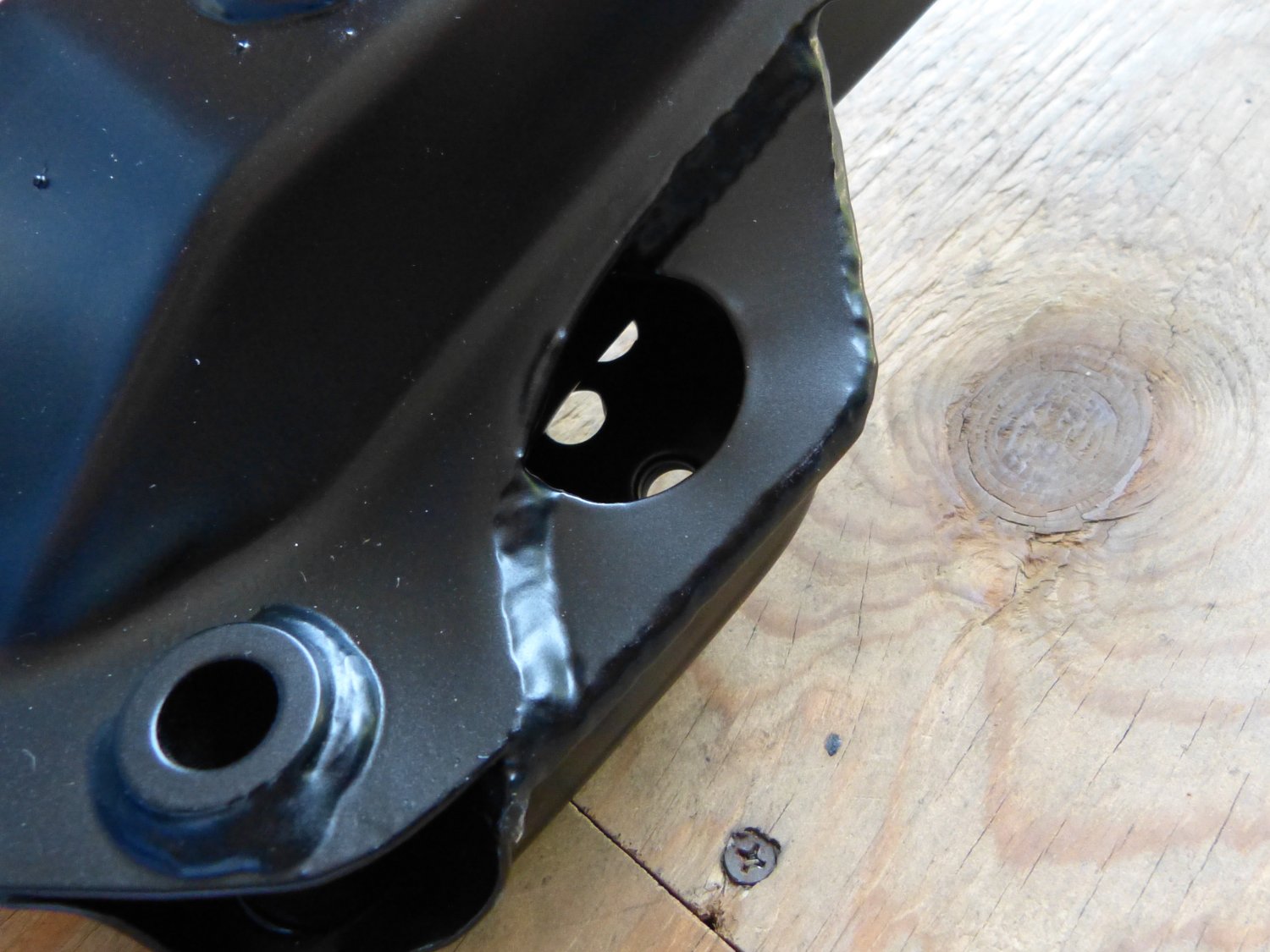 The powdercoater took time to get good coverage in the pocket by inserting the nozzle inside that tiny hole. |
Because I needed to install the engine mount supports first I had to begin by removing the paint from the contact areas. My IR die grinder equipped with a roloc disk made very quick and clean work of that task as you can see. With that out of the way I applied a few shots of brake cleaner to the threaded bores in the block to clean the threads of a bunch of dirt.
I then went on a search for the proper torque value for the bolts that mate the support to the block but came up empty so I decided to use the standard generic M8 grade 8.8 bolt torque spec provided by BMW, or 24 Nm (17 ft*lbs). That torque is quite typical for bolts that thread into aluminum structures so I felt it was safe enough for the cast iron block. Given the contortions I had to go through to remove the left side support I thought for sure I would not be able to get the torque wrench on the bolts but I did manage to torque all the bolts properly.
The thick powdercoating reduced the diameter of the holes in the subframe that accept the engine mount studs so I put a metal abrasion bit in the Dremel and cleaned up the holes as required to make the studs fit snugly. Before mounting the subframe to the body I again used a bit of brake cleaner to clean the bolt holes in the frame rail because I knew any grease or dirt on the threads would affect the torque applied to the fastener. With the threads clean and both engine mounts balancing on the stop of the subframe I perched the engine mount heat shield on the right side mount and proceeded to lift the assembly to the vehicle.
It took a couple attempts to line up the top engine mount studs with the corresponding hole in the engine supports, particularly on the left side, as the engine was somewhat canted. I figured that was caused by the floor jack so I lowered it just a bit and the stud lined up perfectly. Before I installed the nuts on the engine mount studs I decided to torque the subframe bolts next.
As I indicated in a prior blog entry BMW provides three torque values for these fasteners: 100, 105, and 110 Nm. I decided to split the difference and apply 105 Nm (77 ft*lbs). I brought all the fasteners up to the final torque in steps. The bolts took their time firming up and for a while I felt like I was stretching the bolts (and in truth I probably was), but eventually they firmed up and the torque wrench clicked.
Now with the subframe firmly mounted to the vehicle I decided to install the bottom flange nuts on the lower engine mount studs. Following Don's advice I started the nuts by hand, which in itself was a minor challenge given the small diameter of the hole in the reinforcing plate, but I eventually caught enough threads to migrate to a socket. I reached for the nearest socket I could find, in this case a 16mm impact socket but I quickly found that it was too thick to fit in the hole so I grabbed one of my chrome sockets and that worked perfectly.
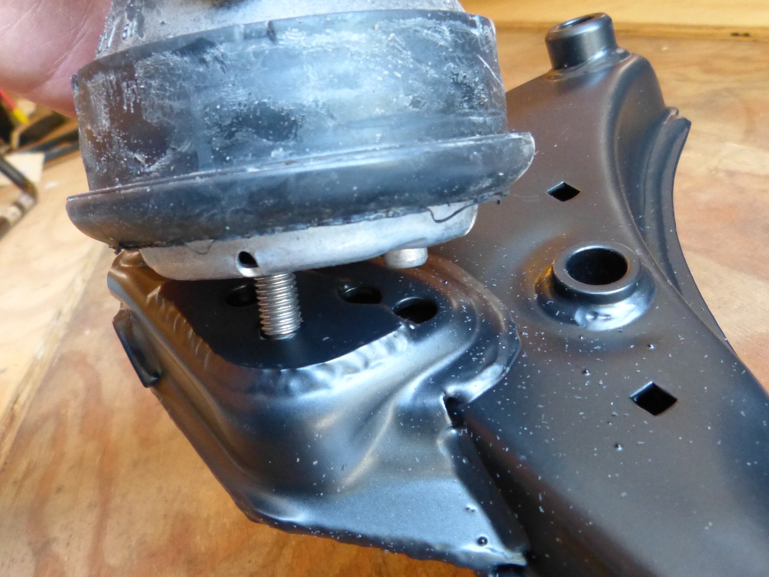 The interface between the subframe and engine mount consists of a stud and an anti-rotation pin. |
 I used my IR die grinder with a abrasive disk installed to remove the powdercoat in the area that mates with the block. |
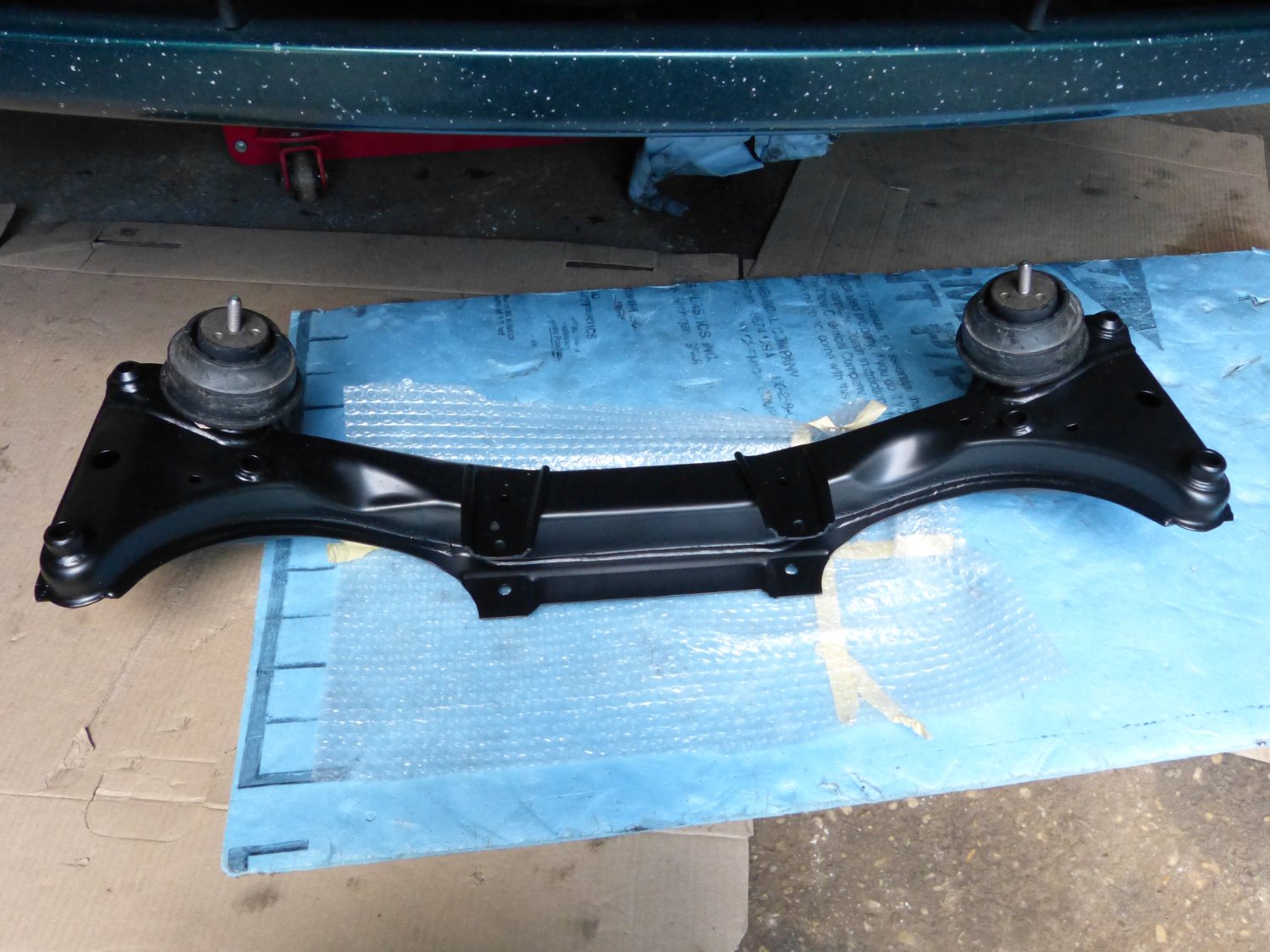 The subframe with the mounts perched on top, just prior to installation. Shortly after this I mounted the small heat shield on top of the right side mount and then raised the assembly to the car. |
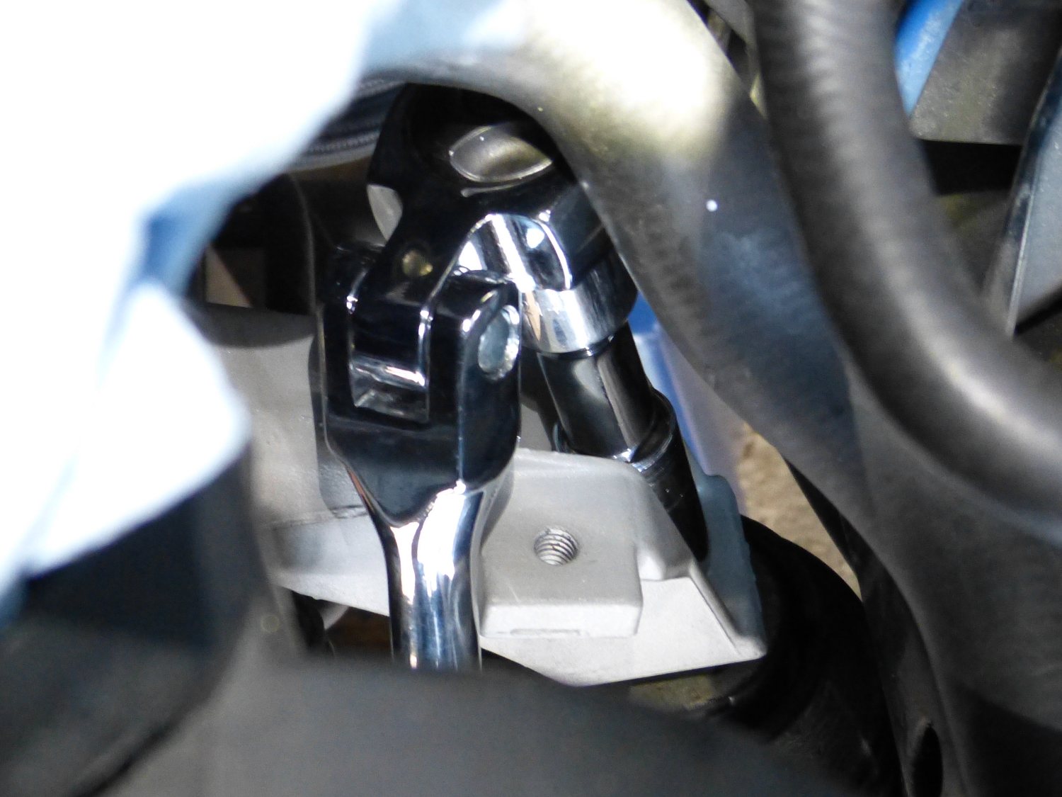 How do you reach those pesky upper engine mount nuts with everything installed in the car? You use an expensive 1/2" drive swivel ratchet shown here. |
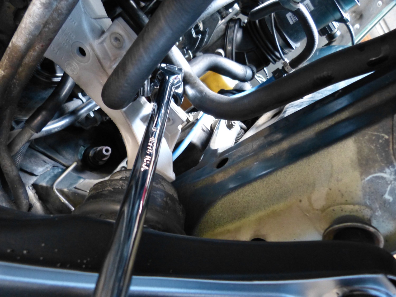 Another perspective of how I used the swivel ratchet, this time from below. Believe it or not, with the ratchet at a good 75 degree angle I could still slowly but surely tighten the nut. |
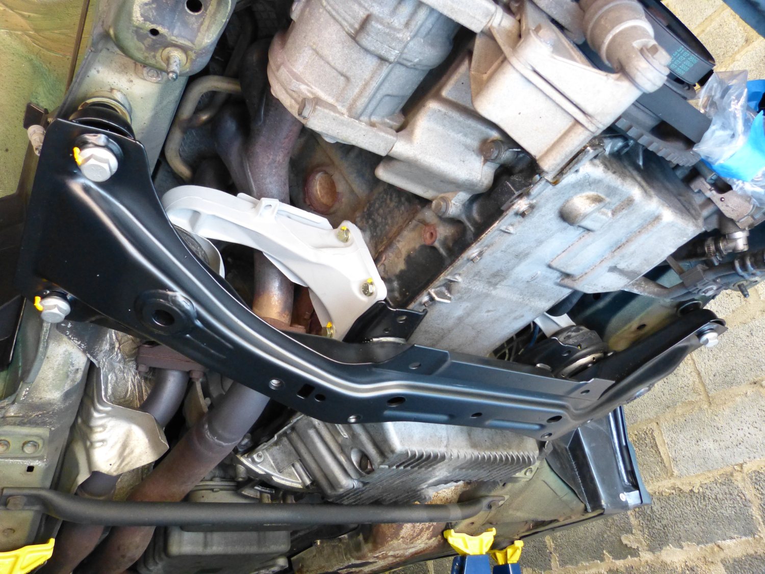 Mission accomplished: the subframe is installed and the full weight of the engine is resting on it. The engine hoist as been removed. The car is slowly coming back to life. |
I had to lower the engine in steps to allow the top engine mount studs to mate properly with the engine supports and I found that due to the manner in which I had jacked up the engine the left side stud did not want to align with the hole in the support until I lowered the jack almost all the way down. At this point, however, the engine bridge support was still holding the engine up a good amount, so that may have contributed to the alignment issue. I simply lowered the engine and then checked the top studs to find them both securely in the holes in the supports and ready to accept the flange nuts.
Installing the top nuts turned out to be a bit more difficult but still manageable with a handy tool – a 1/2" drive SK swivel ratchet I originally bought to R&R the inner lower control arm ball joints. I don't know how I could have done this job without it. At $50 it wasn't exactly inexpensive when I bought it several years ago but today it paid for itself in spades. I did not torque the top or bottom flange nuts on the engine mounts because there was no way to use a torque wrench there. I simply tightened them until they firmed up, and they did so suddenly so there wasn't any guess work involved.
By the end of the work session the engine was once again resting comfortably on the mounts, the subframe was supporting the weight of the engine, and the engine bridge support was removed from the car for the first time in several weeks. Although I still have to deal with the steering column I think it's safe to say I've crossed the half-way mark in this project and that feels good.
Before I left the garage for the day I had one other small job to do: drill out the broken stud that is used to fasten the brake wear sensor junction box to the car. I figured I'd use an AVK stud insert to replace the welded stud but as the studs come in different grip ranges I needed to know how thick the metal was in this case. After breaking two drill bits in my set I finally broke through the metal and realized the metal was only 1-2mm thick. That was the good news. The bad news is I found another piece of metal about 3/8" behind that, and that may be the deal breaker insofar as using an insert is concerned as even the smallest inserts are 9 or 10mm deep in compressed form. I may wind up simply drilling and tapping the hole.
Videos:
- Result of re-attaching heat sink to engine support
- Subframe and engine supports / mounts reinstalled
Mileage: 222600, Labor: $340, Parts: $175