


Saturday, June 30, 2012
Front Suspension Overhaul - Day 10
This morning I stopped at Eppys to pick up a small set of cold chisels and a manual impact screwdriver (total: $60) to aid in my assault on the fracture bolts. I then stopped by the dealer to pick up a few odds and ends I ordered last week. When the receptionist smiled and feigned disappointment in me for spending less than $100 I realized I might be spending too much time and money there lately. Fortunately, I think it's safe to say I'm largely done buying parts for this project and I shouldn't need to make too many more trips to the dealership...that is until I start the "lower interior overhaul" project I have planned for later this year.
When I arrived at the garage I once again tried to attack the fracture bolts, this time armed with my new impact screwdriver. The good news is the tool worked as exactly as it should, but the bad news is it still failed to remove the bolts. I'm now planning to follow the advice of reader Brian, who kindly provided photos and a great description of the technique he used to remove the bolts. According to his technique I've done half the work already by cutting the slots deep into the heads. Now I simply need to cut half of the head off, continue cutting slightly into the other side of the head, and finish up with a chisel to break off the other half of the head. That should allow me to pull the column and then unscrew the remaining studs. I decided against continuing with this today since it was way too hot in the garage and doubly so in the car with little air circulation.
Incidentally, I received the high strength M8 bolts from McMaster-Carr that I plan to use to replace the fracture bolts, but I bought OE fracture bolts as well to serve as a means of comparison. More on this topic when I finally get the column out of the car.
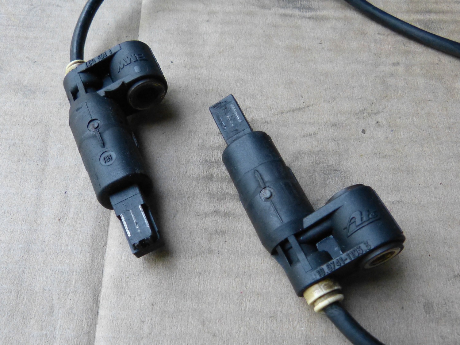 I cleaned up the ABS sensors in order to return them to duty. I removed a ton of metal filings from the ends of the sensors which are obviously magnetic. |
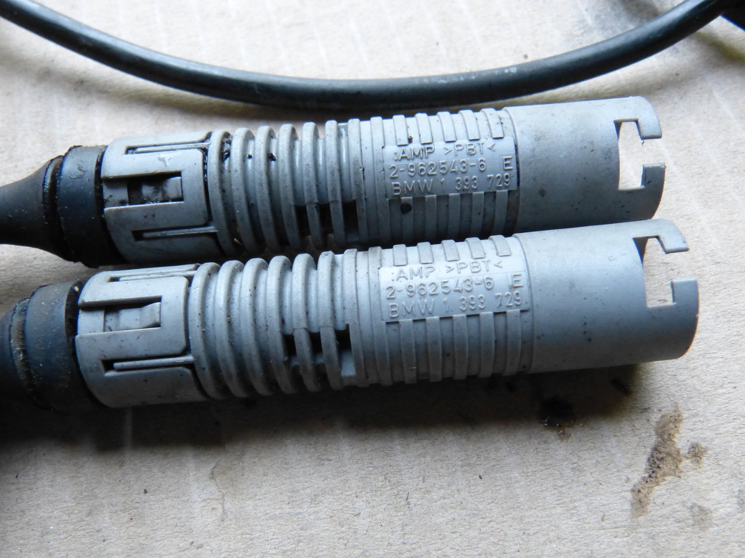 A closeup of the ABS sensor connectors shows their part number for future reference. These can be replaced without paying for an entire sensor if necessary. |
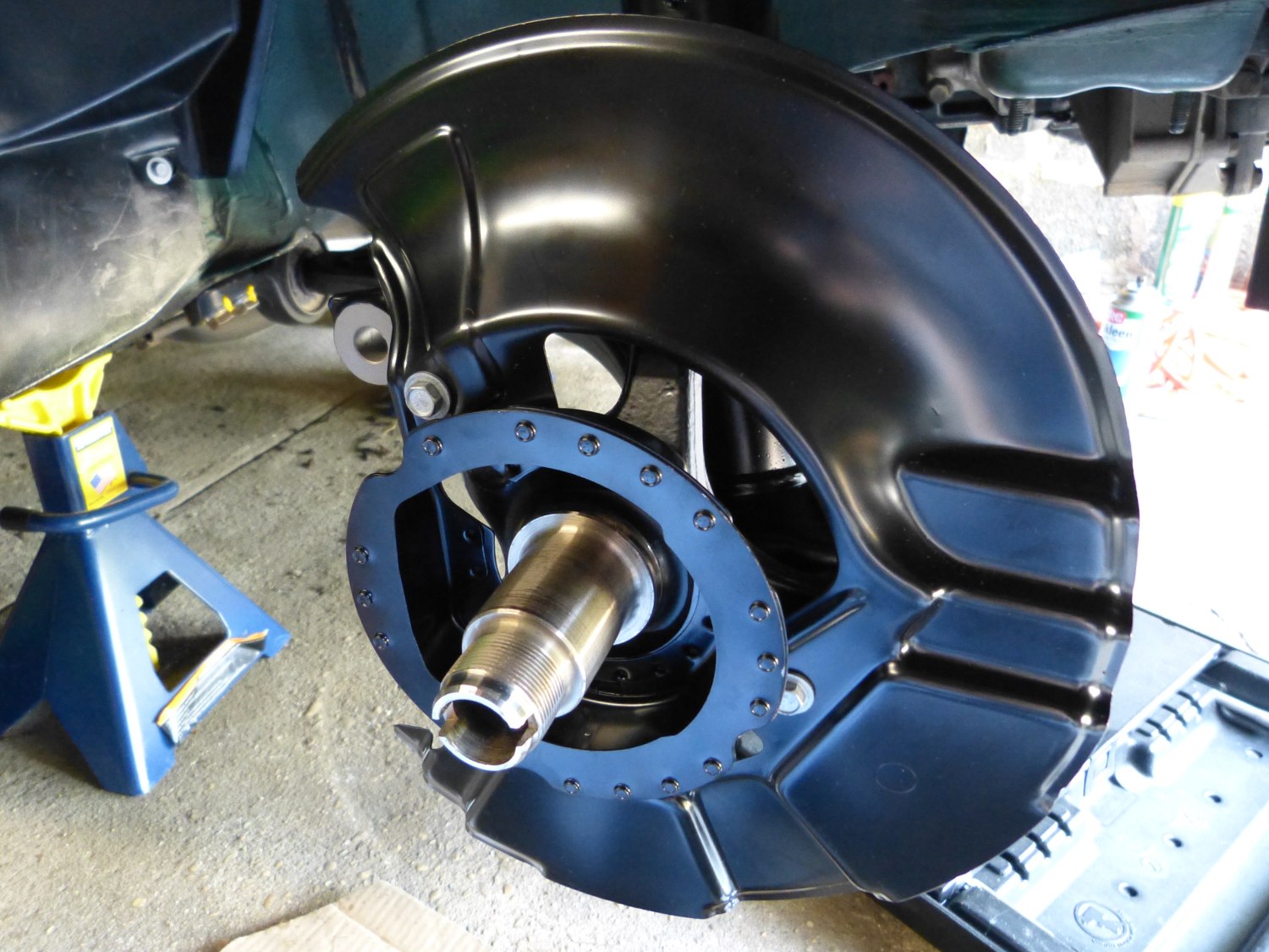 First step in installing the wheel bearings involves the installation of the brake shields. I had to chase a couple of the threads but otherwise this was routine. |
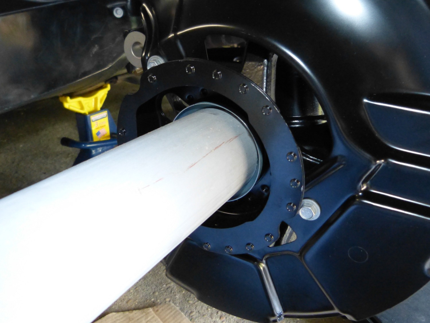 I used a short length of schedule 40 2" PVC pipe as a drift to aid installation of the bearing shields. |
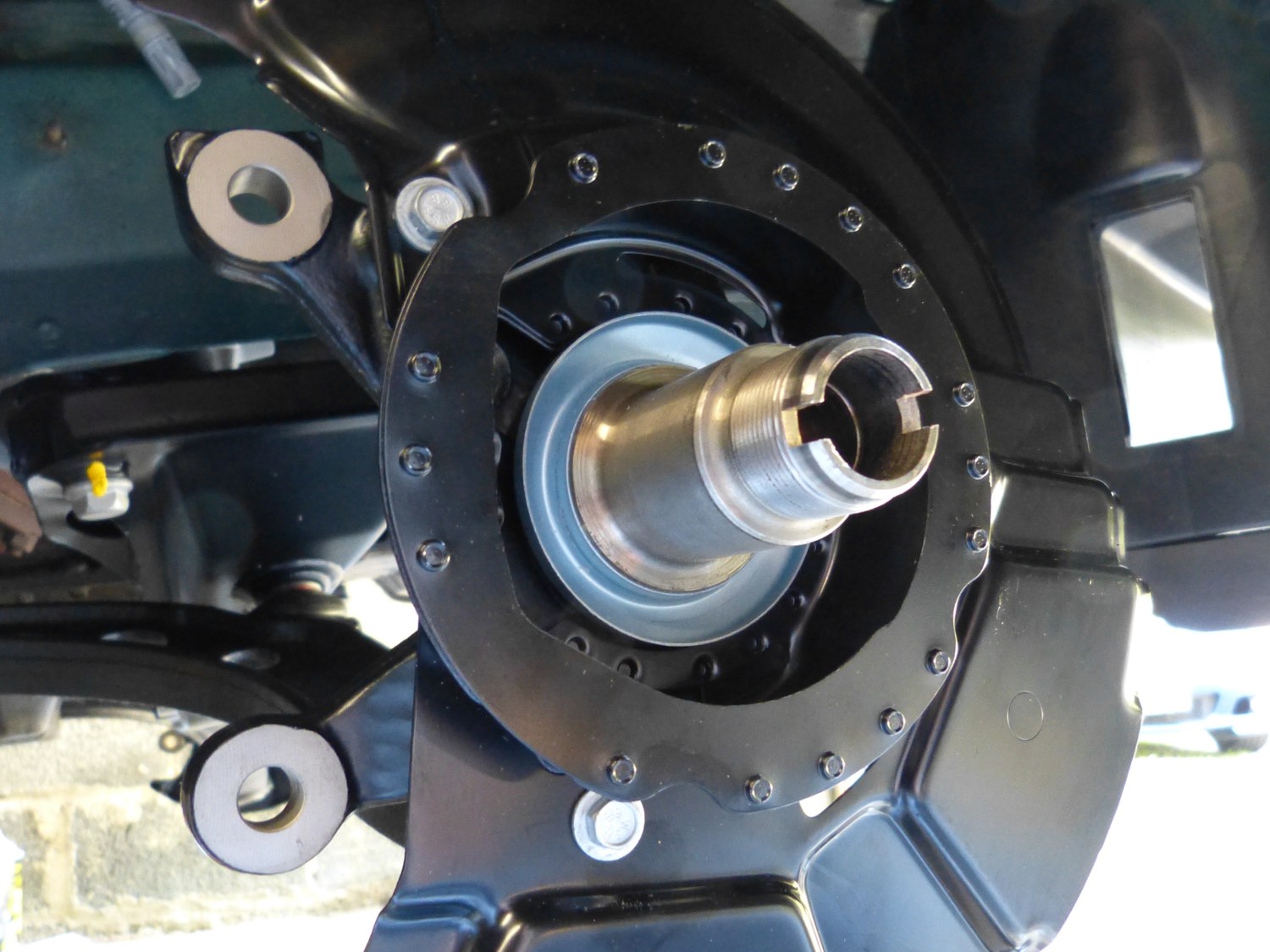 This closeup of the stub axle with the bearing shield installed shows how it sits slightly shy of the larger face of the stub axle where the inner race of the bearing mates. |
 The bearing is now installed. Note that the axle nut (aka the "jesus nut") is not torqued because that needs to be done with the car on the ground. This will happen soon enough. |
With the fit bolt nuts in hand I decided to install those nuts and torque all the fasteners on the front end to spec. Here's a list of the torque specs and some comments:
- Lollypop Bolts: 59 Nm (44 ft*lbs) + 90 degrees with a tolerance of +/- 15 degrees. I used 80 degrees achieved in two 40 degree increments since I couldn't swing the torque wrench 80 degrees total. I did not use 90 degrees because I was paranoid of snapping the bolts, which CAN happen if the bolts do not meet specification.
- Inner balljoints to subframe: 80 Nm (59 ft*lbs). Normally you have to put a floor jack under these ball joints to prevent them from rotating. As luck would have it I didn't have to do that today because I had already torqued these by hand fairly tightly last weekend. I just "topped them off" today.
- Outer balljoints to kingpin: 65 Nm (48 ft*lbs). Note: Unless you have a crow's foot socket (and install it 90 degrees to the torque wrench axis to avoid increasing the moment arm of the torque wrench, which would affect the torque applied) there is no way to torque these bolts so I just tightened them until I felt I had achieved 48 ft*lbs. They tended to firm up quickly so I don't think there's much guess-work involved here.
- Kingpin to strut (two lower M12x20 bolts with red-loctite): 107 Nm (79 ft*lbs). Note: I implied in an earlier blog entry that it was possible to reuse these bolts and that is NOT correct according to the TIS. They must be replaced with factory new bolts, which will come with red loctite on the threads. There is no reason to buy a tube of red loctite for this application, and so far I haven't needed to use it anywhere on the front end.
- Kingpin to strut (upper M12x42 "fit bolt"): 107 Nm (79 ft*lbs). This is the same torque as the other two fasteners but this bolt can be reused as long as you install a new self-locking nut. P.S. The fit bolt can be replaced with a "camber correction bolt", but that's simply a smaller diameter bolt with threads over the full length of the bolt. Since this bolt is stressed in shear and I'm not keen on threads in shear, I decided to retain the standard fit bolt.
- Strut guide support struts to shock tower: 24 Nm (17 ft*lbs). I torqued to 10 ft*lbs and then to 15 and left it at that as I know these are intentionally a light torque and I did not want to risk snapping one of the guide support studs since that would mean disassembly of the strut and another week+ delay. I don't think it matters, but I made a point of aligning the arrow molded into the rubber toward the hole in the strut tower that would normally accept the indexing pin in the top of the guide supports (I removed these).
Before I installed the brake shields I decided to test fit the ABS sensors in the kingpin bores. Neither sensor fit particularly well (what a frickin' surprise) so I installed a sanding drum in the Dremel and cleaned up the bores, after which the sensors fit cleanly and easily. I plan to apply a thin film of grease to the bores to help prevent the sensors from bonding too tightly with the kingpins. I decided against installing the sensors for now because I knew they would just get in the way.
In preparation for installation of the wheel bearings I installed the bearing dust shields, which must be press-fit to the stub axle. I tried to press the shields on by hand but quickly realized that wasn't going to work. As I walked around looking for what might pass as a drift the dusty five watt light bulb illuminated over my head as I passed a pile of old PVC electrical conduit. I found a piece of 2" schedule 40 conduit that matched the diameter of the shield nicely so I used that to install the shields on the car in only a couple minutes' time. Check out the video for the technique.
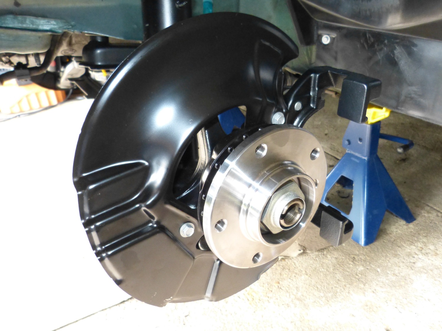
With the dust shields in place I finally got to use the BMW special tool I acquired many years ago to install the wheel bearings. As it turned out the fit between the left side stub axle fit and bearing was very tight so the tool was clearly needed in this case. I used the tool on the right side but the fit was loose enough that I was able to hand tighten the tool's nut to press the bearing to the shaft. All in all the tool made a potentially difficult task very easy, which is typical of most BMW special tools. Check out the full video explanation of how the tool works.
Next up is installation of the brakes and repair of the steering column. Once the column has been reinstalled I'll finish up by assembling the steering system, bleeding the brakes, and taking it out for a test drive.
Videos:
- Pressing the bearing shields onto the stub axles
- Installing the front wheel bearings using the BMW special tool
- Result of powdercoating the caliper brackets
- Summary following wheel bearing installation
Mileage: 222600, Parts: $43