


Monday, July 2, 2012
Front Suspension Overhaul - Day 11
Today I spent several hours at the garage repairing the broken sensor junction box stud, installing the brakes, brake wear sensor, ABS speed sensors, ATF reservoir bracket and bonding strap. Short of bleeding the brakes I've now completed everything I can do before removing, repairing, and reinstalling the steering column.
I decided to address the failed junction box mounting stud by drilling and tapping for the same M6x1 button-head screw I used to fasten the heat shield to the engine support. The screws came from McMaster-Carr in a package of 50 and I knew I'd be limited to about a 10 mm depth in any case, so why not kill two birds with one stone, right?
To prevent breaking my only 13/64 drill bit I dipped the tip of the bit in some ATF and began drilling very slowly (perhaps 1-2 RPM). That worked like a charm. I then opened up my new metric tap set and tapped for M6x1 threads. To avoid the nightmare that would result from breaking the tap off in the hole I dipped the tap in some ATF and slowly spun the tap into the hole by hand, reversing periodically when I felt resistance. When the tap started to spin freely I backed it out and then installed the M6 screw. The result was about as perfect as could be and looked almost "factory". For a brief moment I considered how much better it would look if I broke off the other stud and repeated the process but I quickly came to my senses, installed the junction box and moved on to the next task.
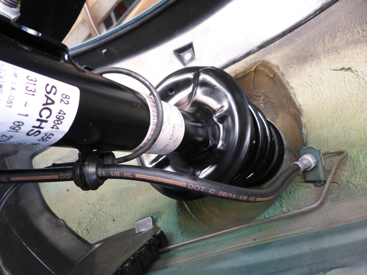
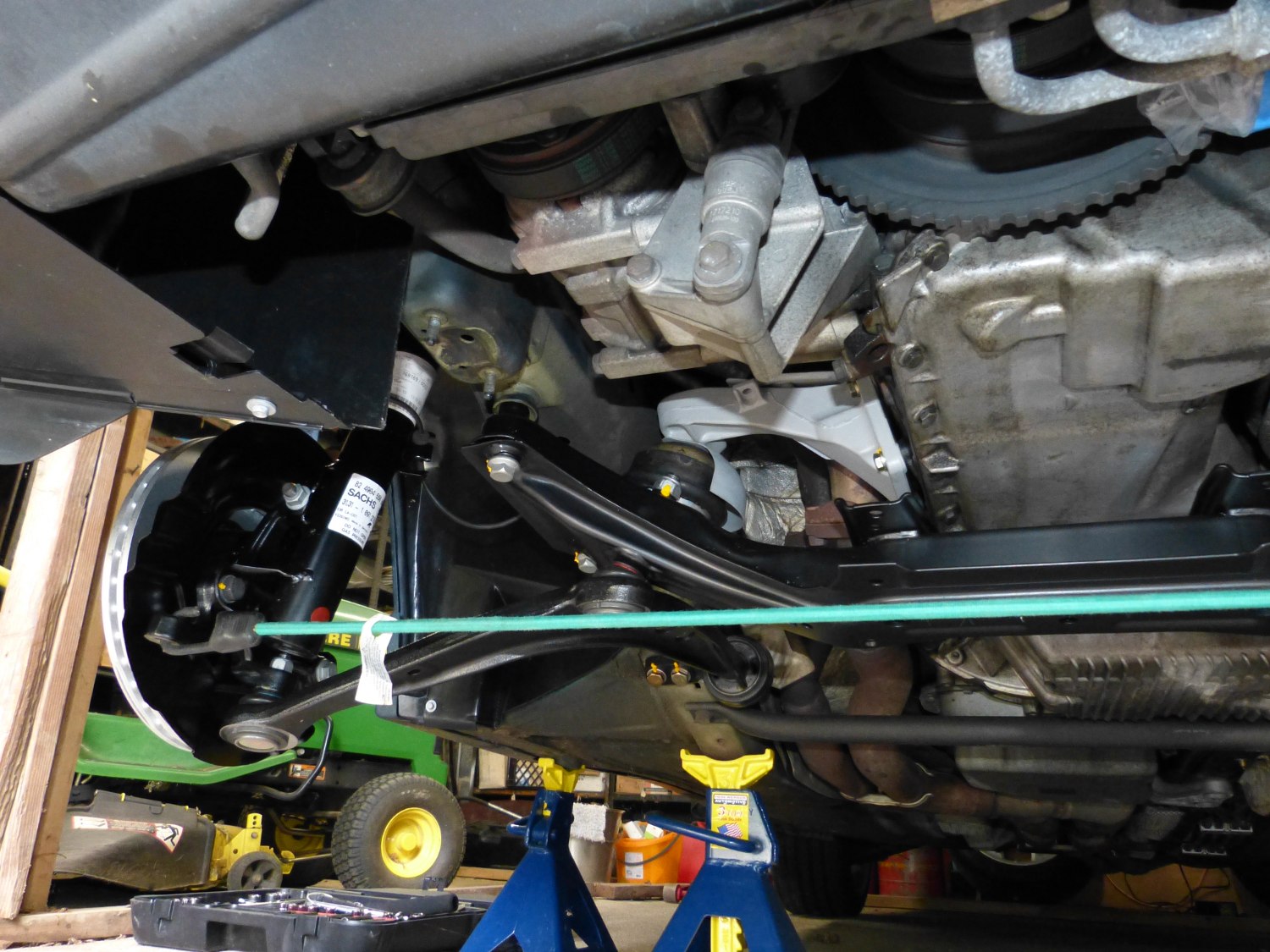 Perspective shot showing new high tech steering rack. I expect it to be a little sloppy in the turns but that should be offset by all the other new parts here. |
 This simple bungie solution helped prevent the struts from turning rearward once I installed the calipers. |
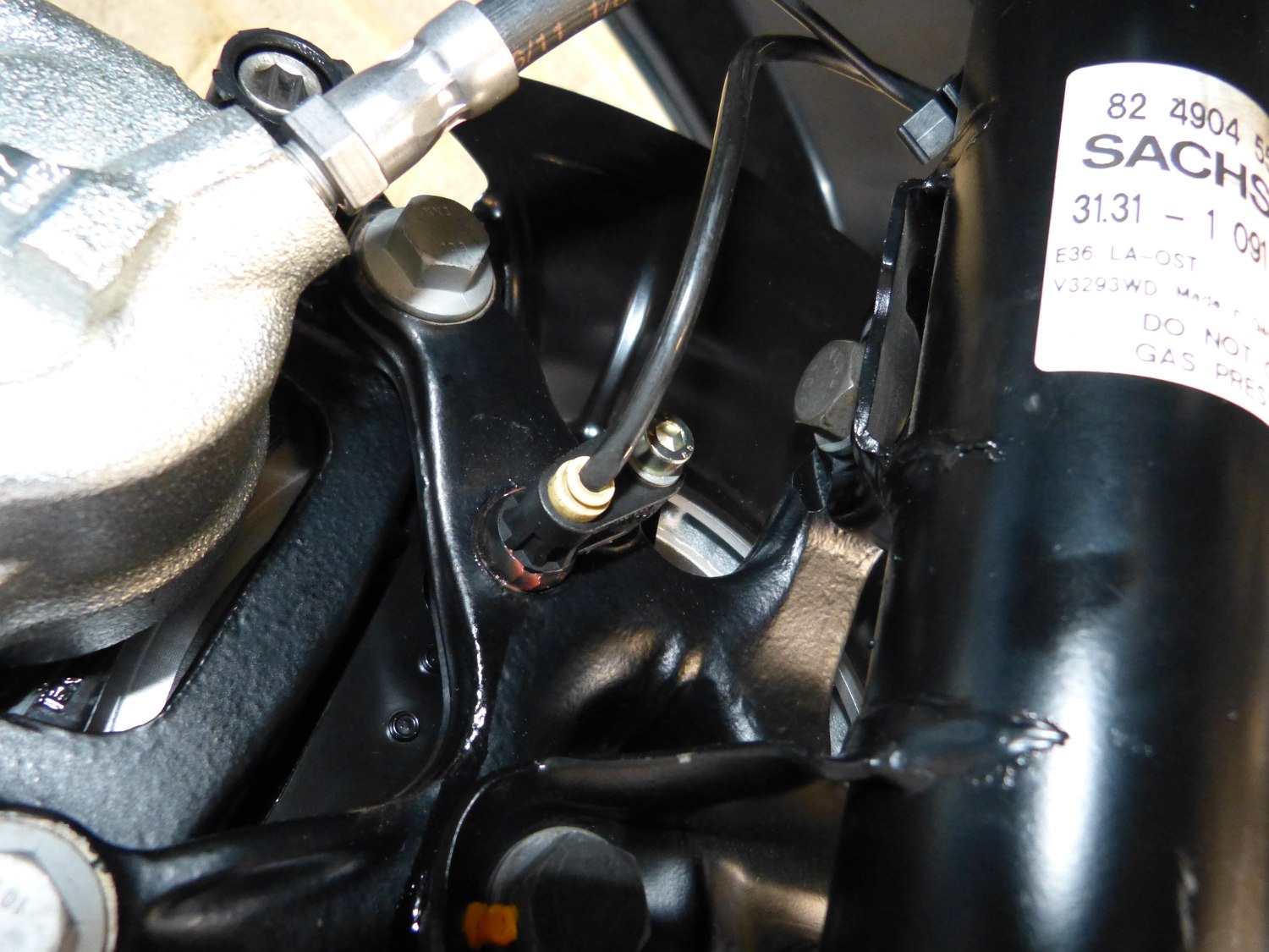
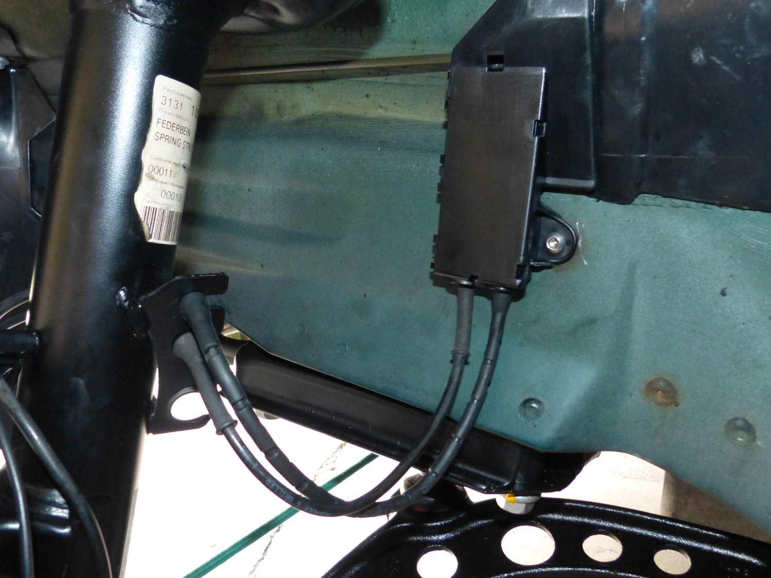 A thorn in my side for the past several weeks, I finally managed to come up with a workable solution for the broken junction box stud, and reuse a spare screw in the process. |
With the junction boxes installed on both sides I decided to install the small plastic wire management clips on the studs welded to each strut, connect the speed sensors and brake wear sensor and then route the wires accordingly. It was at this point that I (finally) noticed an easy way to tell the struts apart without going to the ETK. The metal plate welded to each strut is not identical as I previously assumed -- it has three holes on the left side and two holes on the right to accommodate the lack of a brake wear sensor on the right side.
Next, I applied anti-seize to the face of the hubs and installed the new brake rotors. As usual I also applied a bit of anti-seize to the rotor retaining screws and then secured each rotor to its hub. One point of interest: the latest batch of BMW OE rotors now comes covered in a silver paint that is intended to prevent rust. The paint is designed to wear off the face of the rotors naturally during the break-in process so it does not need to be removed. After mating the caliper brackets to the kingpins I torqued the new bolts to 81 ft*lbs, applied Plastilube grease to all the usual areas and installed the pads and calipers. I cleaned and installed the caliper guide pins before torquing them to 22 ft*lbs. And thanks to the tech who applied the silicone lube to the guide bushings the pins slid into the bushings far more easily than they have in the past. Last but not least, I completed the brake installation by installing new zinc-plated pad retaining clips.
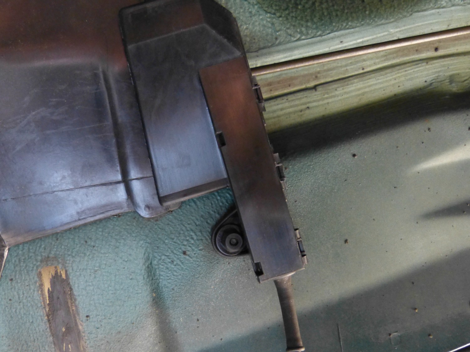 The sensor junction boxes are normally mounted with a plastic nut, as shown on the right side junction box. |
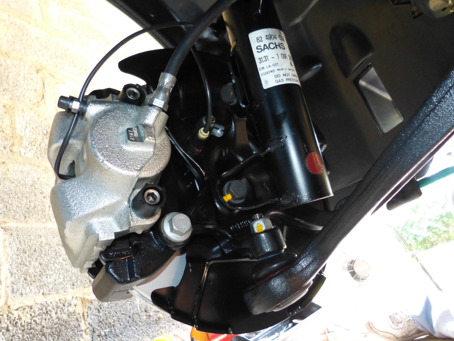 A thing of beauty, no? A rear view of the left front strut and kingpin fully assembled (well, without the tie rod and closures for the guide bushings). |
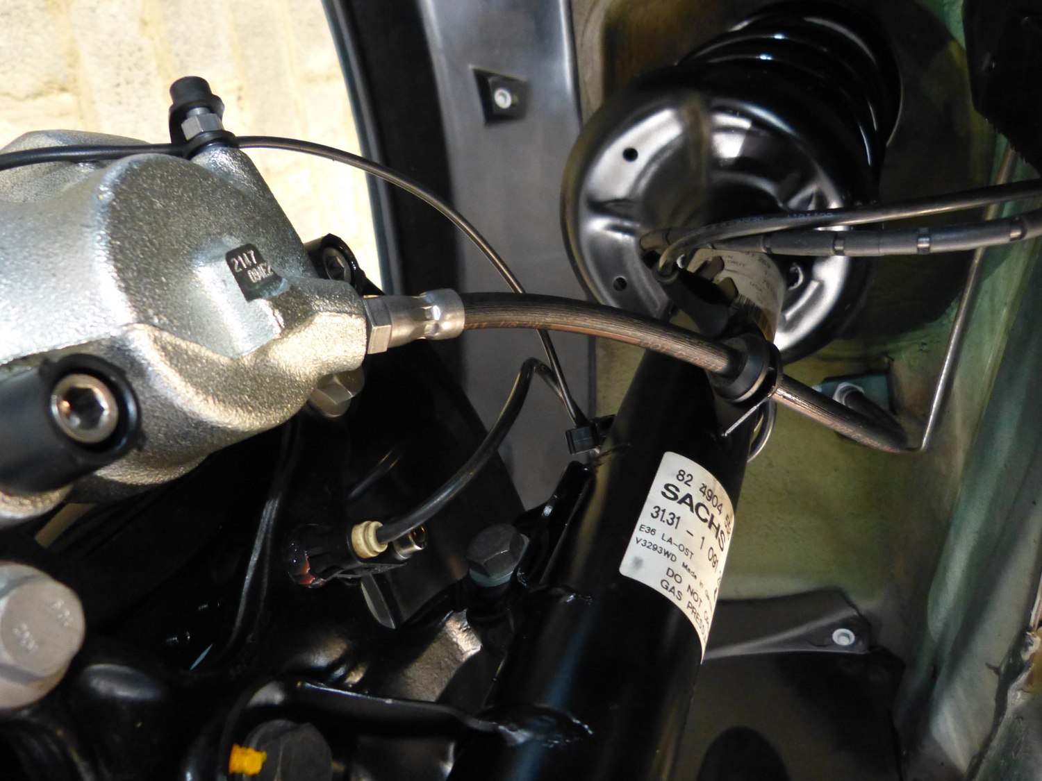
 A different perspective, this time of the right side strut after I installed the new brake line which is connected to a brand-spankin-new caliper. |
While installing the brakes I noticed the natural tendency of the struts to rotate aft because of the caster angle of the struts and extra weight of the calipers so I scrounged up a bungie cord and tied the kingpins together via the tie rod mounts. I found this superior to a piece of wire because it stretched enough to let me rotate the struts as required to work on them but prevented them from flopping around.
To install the speed sensors I opened up a new jar of Redline CV-2 grease and applied a thin film to both the bore and the mating surface of each sensor. Now paranoid of the mounting bolts I put the wave washer on the bolts and then applied a bit of anti-seize to the threads before inserting the sensors and carefully threading the mounting bolts into the kingpins. I found that the bolts didn't really want to thread into the kingpins easily so I "rocked" them (alternately tightened and loosened) several times before sending them home. There is an official torque spec for these bolts but as I know full well the relatively light torque required to break these bolts I decided to play it safe and do it by feel.
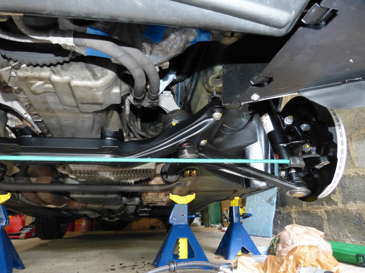
 Another perspective from beneath the left side strut. Note how the wire management tab welded to the strut supports two cables plus the brake line. Compare/contrast with the other strut. |
 A closeup of the speed sensor installed in the kingpin. The red stuff around the bore is just CV-2 grease. Rest assured, I wiped this clean after I took the picture. |
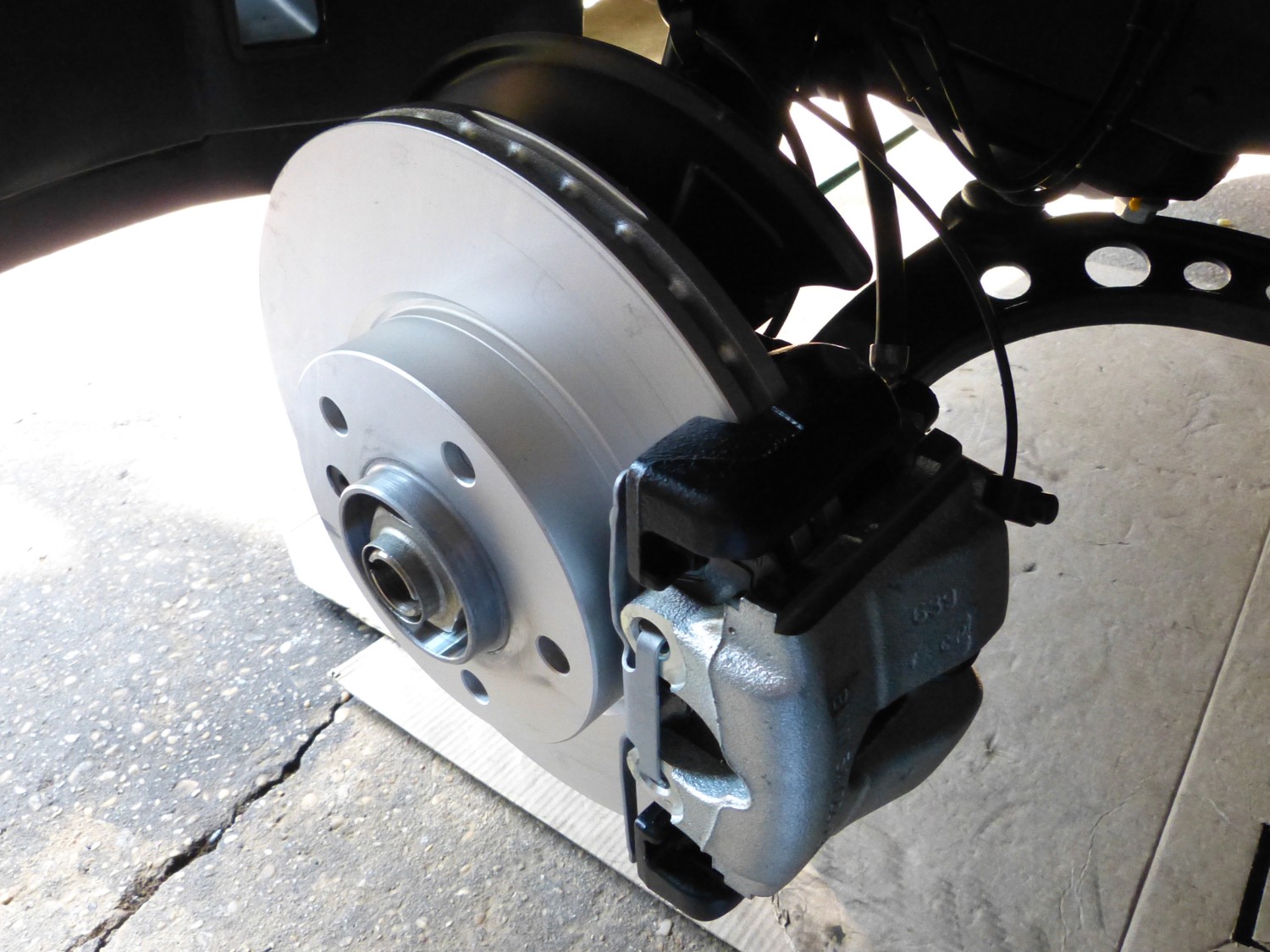 New BMW OE rotors now come with a rust-preventative coating. The coating will wear off the contact area during break-in. |
I then degreased and mounted the ATF reservoir bracket to the engine mount. While doing this I noticed that one of the larger coolant lines was rubbing against one of the edges of the bracket so I cut off a piece of clear tubing I used to create my brake bleeding bottle, routed a ty-wrap through the tubing, and then wrapped it around the coolant line before securing the ty-wrap to a nearby structure to pull the coolant line away from the bracket. I used the tubing because the small ty-wrap could, under the proper conditions, act just as effectively as a sharp metal structure to cut through the coolant line. I'm not exactly sure why this interference problem exists but my experience in working on airplanes is to protect critical stuff like this BEFORE it becomes a problem.
Lastly, I installed the electrical grounding / bonding strap between the frame and engine support. I had intended to buy new OE hardware for this application but the parts guys couldn't find the bonding strap or the associated hardware in the ETK. Since I had just taken delivery of a bunch of M8x1.25 thread bolts intended to replace the fracture bolts I grabbed one of the M8x15 bolts, a spare M8 metal locking nut and used those to finish up this task.
I'm taking the next day off from the project to relax a bit (I'm supposed to be on vacation, after all), but will be back in the garage on Wednesday to get that f*@!$!#! steering column out of the car. Unfortunately we're in a heat wave and the forecast is for 97 degrees, but I'll do what I can before I melt. My kingdom for an air-conditioned garage.
Mileage: 222600