


Saturday, May 20, 2017
Inventory Check
On the way home from an appointment I made an impromptu visit to the dealer. First stop was the parts desk, where I asked the guys to check stock on transmissions. They indicated there were none in the US and three left in Germany. The last time I checked a few months ago there was one in US inventory, so obviously someone out there likes their E36 as much as I do and spent a hefty sum to replace its transmission. How much exactly? $6000.
When I asked what they could do for me they said their cost is $3900 and they'd be willing to let it go for $4100. This represented a profit of a mere $200 (3.3% of retail price) and an overall discount of 32%. That, my friends, is the power of a good business relationship. Unfortunately, the reality is that price is still far too rich for me and I will pay it only as a last resort. But on the other hand, it's nice to know I have the option for a factory reman, at least for now.
I again confirmed that while the torque converters are available separately, the transmission always comes with a torque converter. So it's $4100 or nothing.
Planning Meeting
Next I dropped by my technician's office to speak with him about a variety of topics.
I mentioned the pistons I selected and my plans for boring the cylinders. He advised against boring the cylinders to different sizes because he felt that would have little if any practical benefit but would create potential headaches with ring end gaps. Little did I know at this time Steve from Top End Performance would later agree with him. The conversation naturally drifted toward a discussion on clearances and he said that the mid 80's engines such as the M20 used to make quite the racket for the first minute or so on startup (due to piston slap), but as BMW considerably tightened the tolerances on later engines they got much quieter. He added that tighter tolerances are better but, smiling knowingly, "only to a point".
I then posed a few logistical questions. First I asked how I should go about loosening the crank bolt which is the highest torque spec on the car (~300 ft*lbs). The end result of this conversation and additional research reveals three options:
-
My tech suggested that the quick and dirty way to loosen it is to put a socket on a breaker bar, place it over the crank nut, brace the bar against the frame and then blip the starter. At first I thought he was yanking my chain, but no -- as frightening as that may sound -- it apparently works.
-
50sKid got lucky in a matter of speaking, as he broke it loose with an impact wrench while the timing chain wedged itself in the guides and stopped the crank from spinning. I'm not sure what long term impact that would have on the timing chain or the crank sprocket / keyway, so while I'm planning to replace the chain I'm less inclined to take this approach.
-
A thread on bimmerforums suggested simply using the TDC timing pin tool inserted into the flywheel and a breaker bar (with a possible cheater bar) would be sufficient. Interestingly, this same thread suggested my technician "out of the box" approach as an alternative.
As far as getting it tightened again, I think it's safe to say that everyone uses an impact wrench with short bursts and gets it reasonably close to the torque spec. I am not convinced that the TDC locking pin or perhaps more importantly, its mounting flange on the block, would tolerate being pushed to that limit. My guess is either the pin would sheer, the hole in the relatively thin flywheel would elongate (or both), or the flange on the block would break off in the process. And unfortunately I don't have the option the manual transmission guys do of simply putting it in gear and stepping on the brakes. The auto transmission parking gear only locks the output shaft. The input shaft will spin. So at this point I'm betting on the impact wrench approach.
I then asked for details on how we would get the engine and transmission from the shop into my pickup truck. I wanted to know whether he planned to remove the head while the engine was still in the car, as once the head is removed we would obviously lose the front lifting point. He said that he will pull the engine with the head installed because that is the fastest way to do it, due to limited clearance with the exhaust headers and such, and then we would lift by the front-most point and loop some chain through the lifting point at the rear of the engine located just below the head on the intake side of the block. He then suggested we could then drop the engine down onto an old tire and put the transmission on a pallet with one of the boards removed so the pans would slip into the resulting "slot". He also said that even if the head was removed I could lift the block by using a couple head bolts. Out of curiosity I asked if he thought the transmission could be lifted by two people and he said yes, so my guess is we'll just lift it into the truck rather than try to rig up some kind of sling to use with the crane.
I then asked him whether the vibration this engine is now producing could be caused by a failing crank damper (harmonic balancer). He said there was really no way to tell. He has seen cases where replacing the damper has had an effect and other cases where he thought it would make a difference (i.e. the dampener witness marks had shifted, the rubber was obviously cracked, etc.) and it didn't fix the problem. Considering the damper is a critical part that is needed to minimize potentially damaging vibration and it incorporates rubber which is a known weak point in its construction, I am planning to replace it in spite of the cost. I just can't deal with the concept of doing all this work only to turn the key for the first time and feel that dreaded vibration again.
As far as the time required for R&R he said that the removal should take about a day, maybe a bit more if he is busy with other things in the shop (likely given he runs the place). We didn't discuss the installation but my guess is it will likely take a bit longer as we'll be replacing a bunch of small parts including vacuum hoses and other fittings along the way. It's a big job any way you look at it, and a responsibility that I am happy to delegate.
To wrap up I proposed scheduling the job for late June or perhaps early July after the holiday weekend based on when the needed parts arrive.
Piston Clearance Clarification
While finalizing a list of instructions I plan to give to my machinist I emailed Steve at Top End Performance to clarify clearances again. At this point I was still under the impression that I would instruct my machinist to bore each cylinder to a size that equaled the piston size plus the desired clearance. I asked Steve simply "is this the way I should do this?". A few minutes later my phone rang. It was Steve. He called to give me an emphatic "NO!".
He went on to say that the piston and rings are being engineered to fit in the bore I specified (84.500mm). Like BMW's original parts, the piston will be slightly smaller than the specified bore, and I must NOT to add any clearance beyond that number. If I do I would be commissioning the manufacturing of some "expensive ashtrays". Obviously speaking from experience he said a lot of people like to point blame elsewhere (i.e. at him) when making these kinds of mistakes, so he wanted to make sure I don't do anything unexpected.
Although my earlier conversations with him led me to believe I was in control of the clearance, this does not appear to be the case. I now expect to tell my machinist to bore all cylinders to 84.500. However, I plan to measure the pistons myself to ensure, before we bore the block, that the 84.500 bore will produce a clearance in the range specified in their documentation. If that is not the case I will ask Steve for instructions. Considering this is simpler than my original plan, in agreement with my technician's recommendations, and should make the assembly data easier to collect and compare on the fly, I'm happy.
Ring End Gap
Using the bore size of 84.500 (3.32677") and the ring end gap criteria in the JE installation notes I calculated the minimum ring end gaps for future reference:
|
Ring |
Muliplier |
Gap |
|---|---|---|
|
1st |
Bore x .0050" |
0.0166 (16.6 thou) |
|
2nd |
Bore x .0053" |
0.0176 (17.6 thou) |
|
Oil Rails |
Bore x .015" |
0.049 (49 thou) |
The second ring end gap must be larger than the first to prevent a buildup of pressure between the rings. This requirement can be clearly seen via the smaller second ring multiplier value. With my bore size this should translate into a roughly 1 thou difference between the two values.
As each thou added to the cylinder bore causes the ring end gap to vary in relation to Pi (3.14 times), even small differences in bore sizes can have significant, if not dramatic, effects on ring gap. For this reason, even if the block returns from the machinist with perfectly sized bores I'll check each ring and confirm that the gaps are at least as big as the above numbers. My assumption at this point is that the gaps will meet the specs out of the box, so I'm not planning on buying a ring filing tool but I will if necessary.
Tapered Ring Compressors
Speaking of rings, this week I was finalizing my tools list for the build and I came across the spiral metal band type ring compressor I located several weeks ago. Given the generally lackluster rating of these units I decided to go back and read the reviews in detail. I read a few accounts of people complaining that the compressor came apart, or that they cut themselves on its sharp edges, but those I mostly dismissed. What I could not ignore, however, were several reports that the unit destroyed their oil control rails and they were forced to buy another ring set to replace the damaged parts.
One of the reviewers explained why this happens: as the band is tightened around the piston and rings, the inside edge of the band can butt up against the end of the relatively thin oil rail and deform it. Of course, it's possible to avoid doing that, but I wonder how many noob engine builders (like me) don't realize the danger and just get lucky because they only have to use the thing a few times.
There is a better mouse trap, as they say: a tapered ring compressor as made by Wiseco, ARP and others. These are basically aluminum collars machined such that the lower inside diameter matches a specific cylinder bore size while the upper inside diameter is somewhat larger. This, of course, allows the rings to compress smoothly and safely as the piston is pressed into the tool. The downside? You have to buy one compressor for each bore size you work on (84.500 in my case) but as I'm only planning to insert pistons into a new bore, and I'm only working with a single bore size, that won't be a problem.
I found the Wiseco 84.500 unit selling for around $32 at Summit Racing. I'm not yet sure how much the shipping will be, but I'm pretty sure the total cost will still be cheaper than the ARP units which run over twice that price. The only difference between the two units appears to be the lower edge which is flat on the Wiseco unit and machined with a lip of some sort on the ARP. I'm not sure what that lip does and to be frank, I don't care, provided $32 part will get the job done as I suspect it will.
Given my quest to save money you might wonder why I would spend $32 when I could spend about half that on a band type compressor. The answer is simple -- replacing a damaged ring set would cost more than $15 in parts and my wasted time, so I consider this cheap insurance.
Work Bench
Since I first approached my brother with my plan to set up a temporary workstation in his garage for this project I have been wondering how I would construct my work environment, including a proper workbench I consider essential to keeping everything clean and organized. I initially toyed with the idea of building a bench out of common lumber but I quickly realized that, while this would probably be the least expensive option in terms of materials, it would cost me additional time to fabricate and that would make it significantly more expensive overall.
I have a couple of Global Industrial's production workbenches in my home lab and these are nice units, particularly because they have leveling feet, adjustable legs, and are available with a variety of table top materials ranging from plastic laminate (including ESD safe versions), butcherblocks and resins. I initially considered buying another production workbench with the relatively inexpensive plastic laminate top, as that won't absorb oil, but it seemed a waste to pay to ship a table top that I will have to modify to mount a vise and ultimately discard. The best compromise seems to involve buying only the leg kits and then cutting down a couple sheets of 3/4" plywood for a shop top that I could discard or repurpose easily enough, and then repurpose the leg kit with an ESD-safe laminate top purchased at a later date.
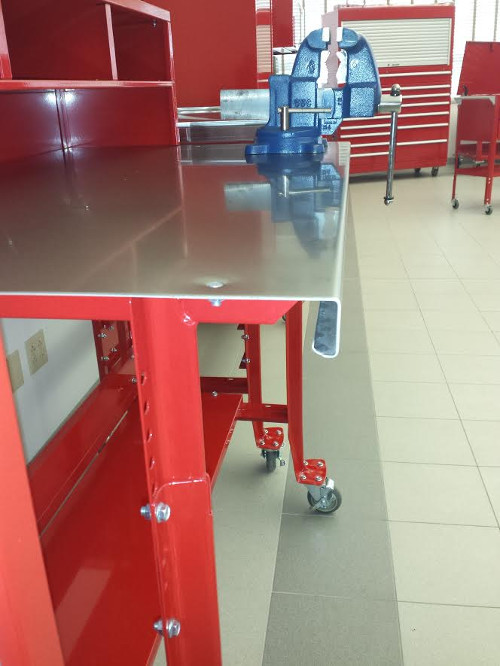
Seeking alternatives I came across Shure Manufacturing who sells a line of professional cabinets and tables. I found their ShureShop tables close to what I was looking for so I inquired about them. It turns out that the "standard" tables are built with 12 gauge steel (about 2.5mm thick) and available with a short 2-5 day lead time. Like Global's production workbenches these tables these can be broken down and should support any component of the engine or transmission I might set on them, though the standard tables are only rated at 1000 pounds, while Global's benches will allegedly support a distributed load of 5000 pounds. An accessory kit, which is optional on the fixed tables and standard on the portable tables (those equipped with casters) includes a some fences that mount to the sides and rear of the top, as well as a lower shelf.
I was initially concerned about mounting a vise to the table because I didn't know if any structure near the front edge would prohibit it, but the Shure rep said shops do this all the time without issue and sent the adjacent picture. Given that the top lacks any stiffeners running the width of the top I would probably add a doubler on the underside to spread the load in any case.
The 72x30 inch stationary table with accessory kit and painted steel top is around $330 + $175 freight. Expensive, but not outrageous either. The stainless top shown in the picture would be a nice addition, particularly because I wouldn't have to worry about scratches and the resulting paint chips from finding their way into the engine or transmission, but it would more than double the cost of the table and so it's simply not worth it to me. The downside to this bench vs the Global solution is I can't really repurpose it for my lab but I could use it in my garage eventually. In the meantime I'll likely leave it in my brother's place. Who knows...perhaps he'll grow jealous of it and we'll work a deal.
Curiously, Shure also provides a tear down bench called the "TransMax" which is sloped toward the rear to allow oil to flow into a trough and then through a nipple and hose to a drain pan. These are great purpose-built tables and very helpful if you're doing transmission overhauls day in / day out, but they're about twice the cost ($650) of the standard flat tables, as well as heavier and hence more expensive to ship. And for more conventional work one might consider the rearward slope an annoyance. Considering that I'm planning to rebuild exactly one transmission and I expect the vast majority of the oil to be drained from it before I ever put it on the bench (assuming I actually put it on the bench at all -- I still want to use the GM mounting fixture even for disassembly), I can't justify the purchase of the TransMax table.
As this will be the centerpiece of my work environment I need to make a decision soon -- probably this week.
Digital Torque Angle Gauge
If you're wondering where I'm getting the money to spend on a commercially manufactured workbench I suppose it's coming from my decision to replace the SnapOn Torque Angle wrench with a digital torque angle gauge manufactured by Brown Line Metal Works.

This well-reviewed unit sells for less than $100, can be used with all of my existing torque wrenches, and even supports a ratcheting mode (something that Eastwood torque angle wrench I mentioned earlier does not). The documentation for the product is above par, as is the physical interface. Its large buttons and generally simple operation should make achieving the torque angle specs relatively quick and easy. There are, of course, other digital torque angle meters on the market for less money but their interfaces are horrible and their buttons tiny, which makes for difficult operation with gloved hands.
I confirmed with the manufacturer that the unit works equally well whether the torque wrench is scribing a horizontal or vertical arc. While I believe all of the fasteners in my build that require a torque angle will be in the more traditional vertical orientation as displayed in all of the literature and videos for this device, it's good to know it is flexible enough to work in other orientations.
I must concede, however, that the guage not as feature rich or tightly integrated as the SnapOn wrench. Some of the differences include:
-
While the SnapOn records every torque and angle in a sequence, the gauge apparently only records the last angle. Once you press the select button to reset for the next torque, the last value is gone.
-
While it provides visual and audible feedback that will be sufficient for most applications it is definitely not as slick as the staged lights of the SnapOn. Personally, I'd like to see a bar graph LED arrangement that progresses from green to red, but the LEDs must be spread out sufficiently to draw the eye's attention. SnapOn manages to do this with a mere five LEDs.
-
Since it's not measuring torque it can't record the peak torque used to remove bolts, and hence help to validate the consistency of torque applied to each fastener.
But these are nice-to-haves, not need-to-haves, and I'm willing to sacrifice those to save $450. On the other hand, if SnapOn wasn't so in love with their products or I was planning to build engines for a living I'd buy the wrench instead.
Mileage: 265750