


Tuesday, August 1, 2017
Bottom End Disassembly Begins
Today I began disassembly of the bottom end. The first task was to degrease the exterior of the engine so I laid out some plastic just outside one of the garage doors, pulled the engine over it and used a high concentration of Zep degreasing liquid and a brush to remove a bulk of the dirt and oil. This process also managed to remove a bulk of the loose old paint crust on the sides of the block and all the greasy dirt hiding behind it. Once I rinsed the block down I used shop air to blow it dry before pulling it back inside.
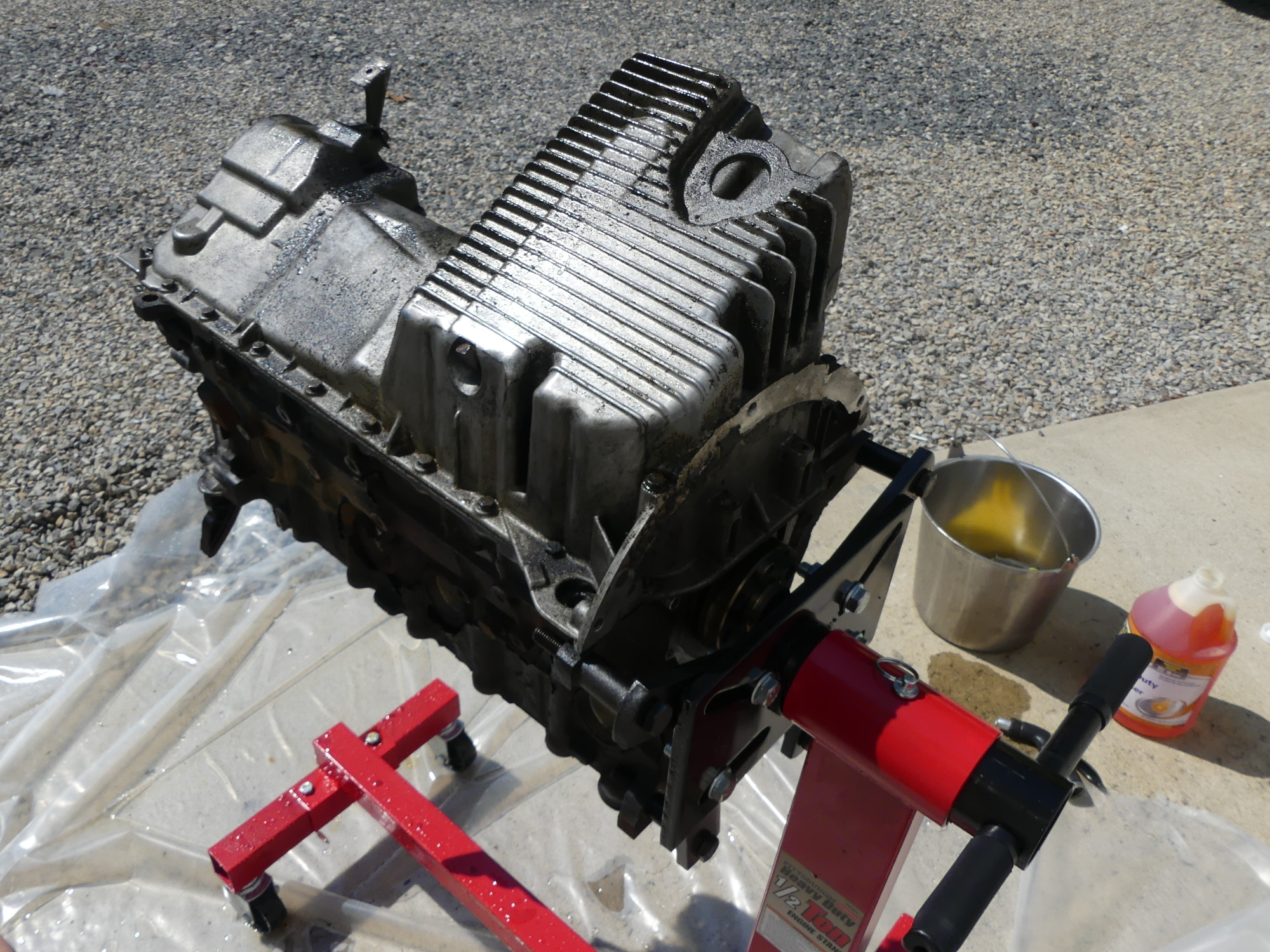 The block sees the light of day so I can clean it. Not wanting to trash my brother's brand new concrete pad I laid down some thick plastic and rolled the stand over it. A lot of greasy gunk, rust, and paint chips came off the block during this process and the plastic did its job. |
 Good enough. The goal was to clean a bulk of the grease and grime from the parts so they wouldn't be so nasty to handle and transport to the machinist for the real cleaning process. This process removed most but not all of the original paint that had long ago separated from the block. |
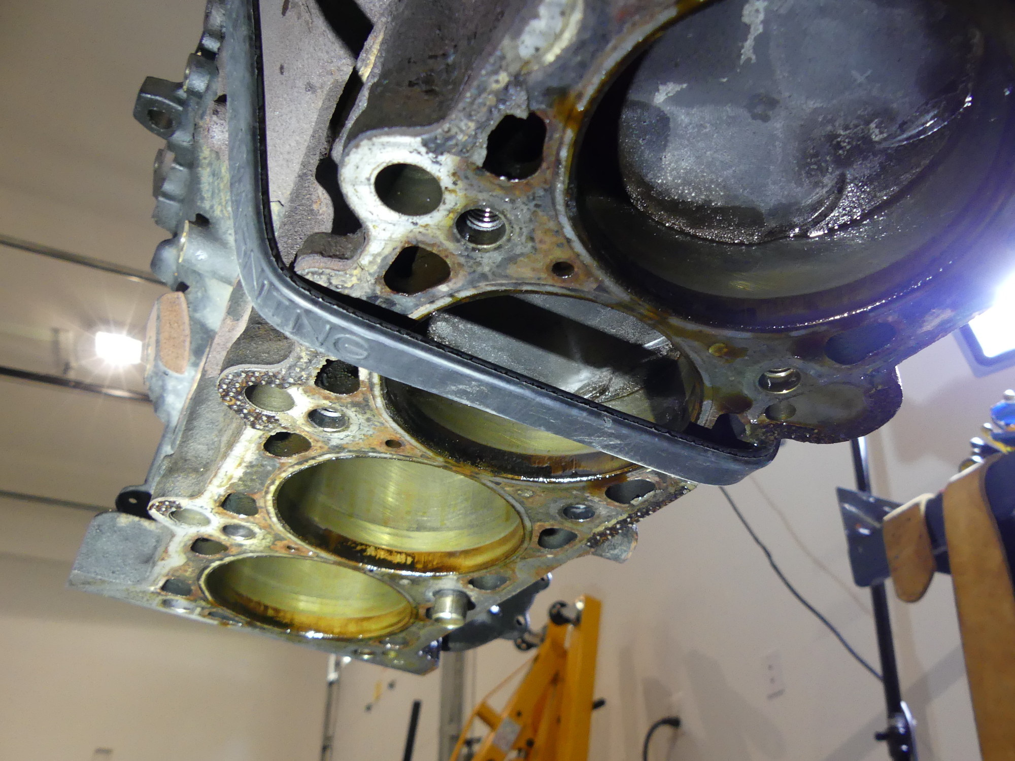
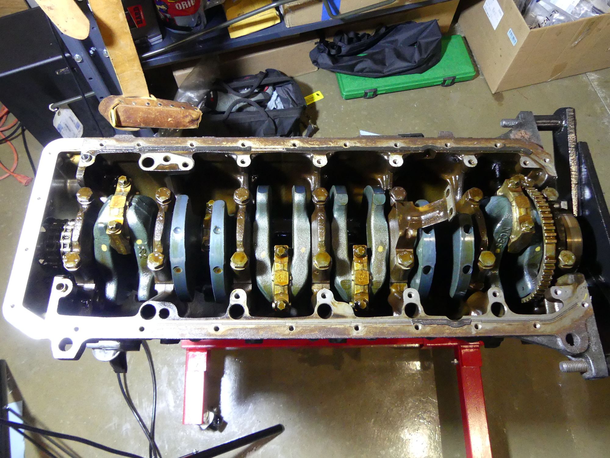 Skipping ahead following removal of the oil pump and windage tray, this is the bottom end of my M52. The crank has a strange bluing to it. Not sure what that is. Forged cranks like on the S54 have a blue tint to them, but that's different than what I see here. |
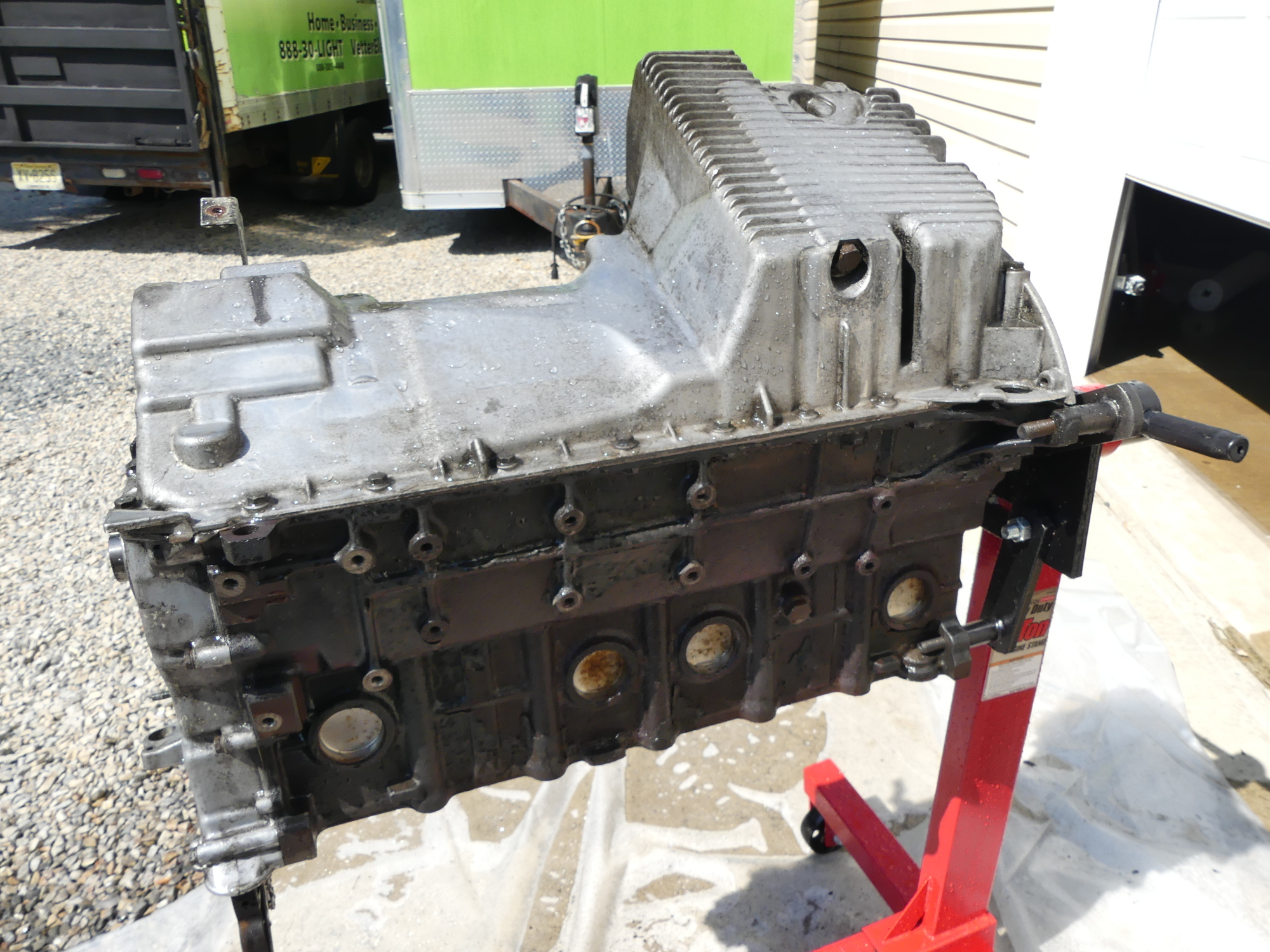
I managed to rotate the engine upside down on the stand for the first time and found it to be fairly easy, probably because I no longer had a top-heavy engine and I had applied grease to the stand's mounting plate boss. All of the oil pan bolts came off easily enough and the oil pan itself practically lept into the air as I pulled it up and off the block. I set that aside and then attempted to remove the oil pan gasket which remained behind on the block. I haven't looked at the new gasket to determine how it's constructed but the old one consisted of a thin metal frame and a ribbed seal around its inside edge. This seal had definitely seen better days, and I can now understand why it was leaking. As I pulled the frame off the block much of the ribbed seal fractured and remained behind.
While I wanted to remove the windage tray next I realized that the oil pump pickup tube extended over it and fastened to a mounting boss that went through the tray, so the pump and pickup tube had to come off before the tray. Once the tray was removed I realized that the M52 bottom end is a bit different than the M54. Having seen so many videos on the M54 I naturally expected to find the little v-shaped mains reinforcements but as it turns out the M52 does not have those. To remove the tray I had to remove ten 10mm bolts.
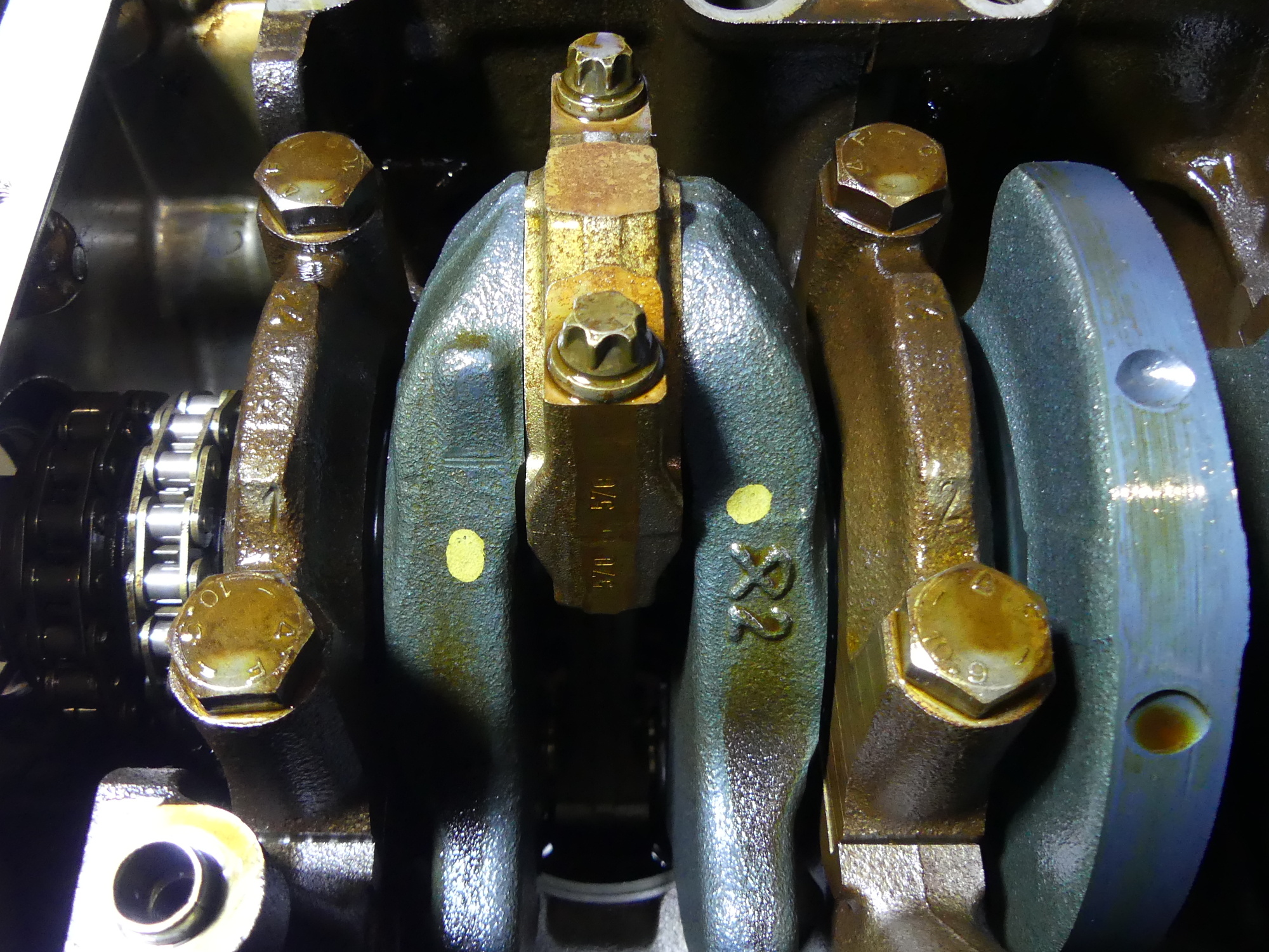 Behold the yellow paint dots. These indicate that the crank is the first standard grind. BMW cranks wear, well, like iron, but I'll have to measure the crank to see if the diameters of the journals are consistent with the first grind specifications. |
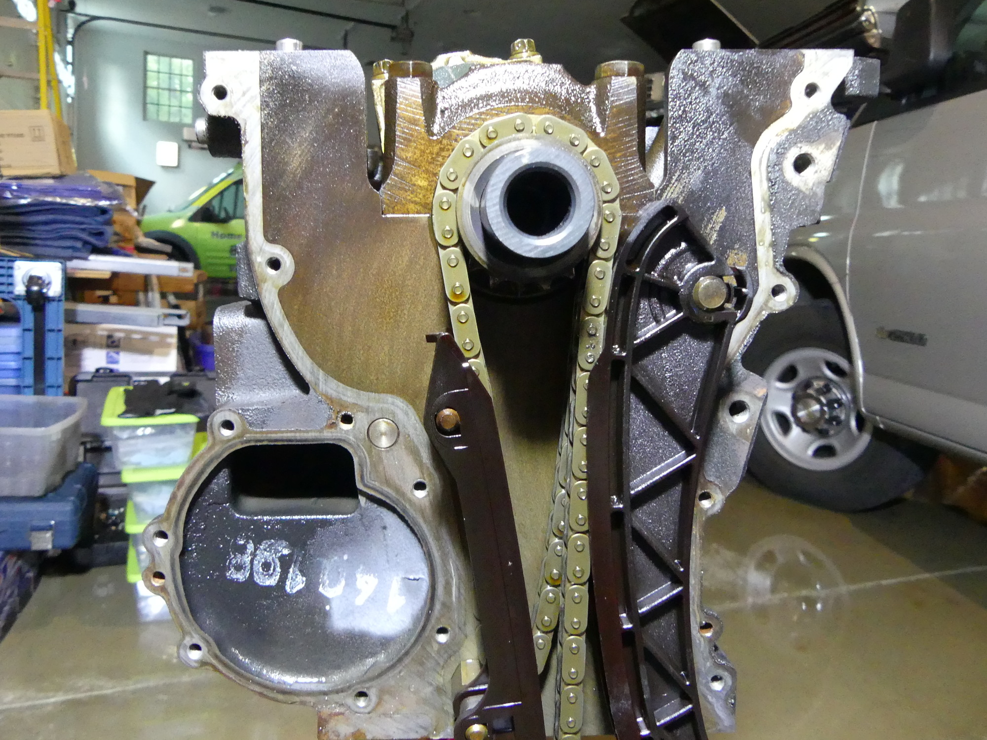 Showing the primary timing chain and the original guides. These guides cannot be removed without breaking them, it seems. No matter. Unless you're rebuilding a race motor every weekend they should be replaced so this doesn't really matter. |
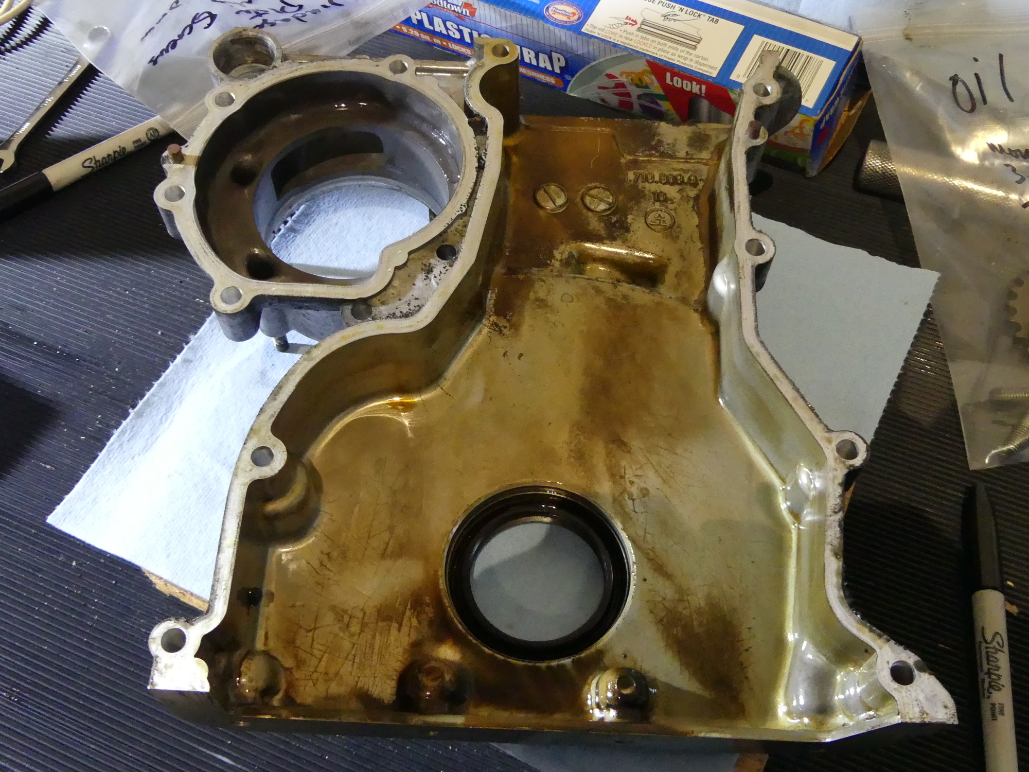 Mostly because I changed oil on a more frequent interval there is basically no sludge in this engine. The oil pan looks cleaner than the inside of this timing cover. Once this goes to the machinist for cleaning it should look brand new. Of course, the crank seal will be replaced. |
Next up was the timing cover on the front of the engine. This used four "long" bolts (about 60mm in length) and 10 "short" bolts about 30mm in length. For those wondering where the short and long screws go it's a simple matter of looking at the thickness of the mounting bosses in the cover. There's no way to make a mistake here. Once I removed the timing cover that provided access to the timing chain guides, both of which were predictably worn to about the same depth as the guide on the secondary timing chain tensioner. As many have discovered the guides do not appear to be removable without breaking the little tab that holds them on. This may be by design or a consequence of the material being brittle after a long time in service. In any case, since I knew I would not be using them again I just broke the tabs, used a screwdriver to lever them off the standoffs and threw them in the garbage with all the other unusable bits and pieces.
After I removed the timing chains I took a good look at the double timing chain sprocket that is mounted to the crankshaft. First, I noticed that pulling this off took some effort. It's not a press fit but it's definitely machined closely to the crank so there is no slop. This sprocket does not appear to be significantly worn (the shape of the teeth seem symmetrical at least), but for some reason it integrates a rubber base of sorts that I imagine prevents some kind of chain noise. I'd normally consider reusing this but the rubber material feels more like plastic at this point, so given that it's not terribly expensive I am likely to replace the sprocket. I also plan to replace the upper primary timing chain sprocket for the same reason.
The next task was to remove the pistons from the bores. I expected this procedure to be very simple but I ran into a problem that affected all cylinders. Simply put -- due to wear on the cylinders the rings didn't want to push past the wear line near the top of the cylinder. I simply could not push the rod down with enough strength to push it beyond the deck of the block so I had to improvise. I grabbed one of my dead blow hammers, found a small piece of wood under my table that was there for no particular reason, pushed the rod down so it was well clear of the rod journal, then reinstalled the cap and loosely tightened the bolts to prevent the cap from jumping off the rod. Then I positioned the piece of wood over the supported edge of the cap (not on the flat center of the cap) and tapped it down with the hammer. This caused the piston to move beyond the wear groove and...you can probably figure out what happened next.
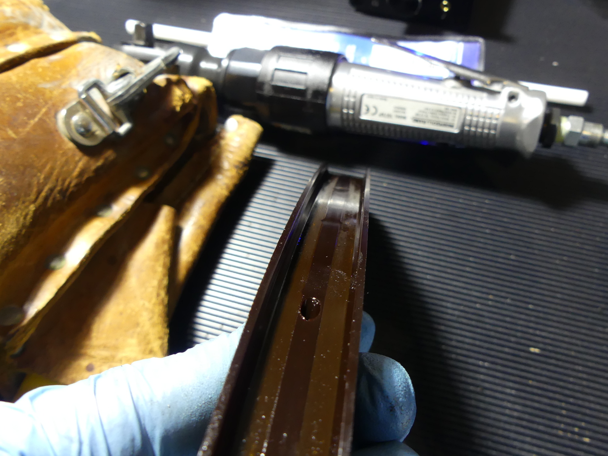 I don't know what kind of material these guides are made of but despite being quite brittle they hold up well. The primary timing chain is continuously in direct contact with this guide and yet the wear is actually quite minimal for 265000 miles. |
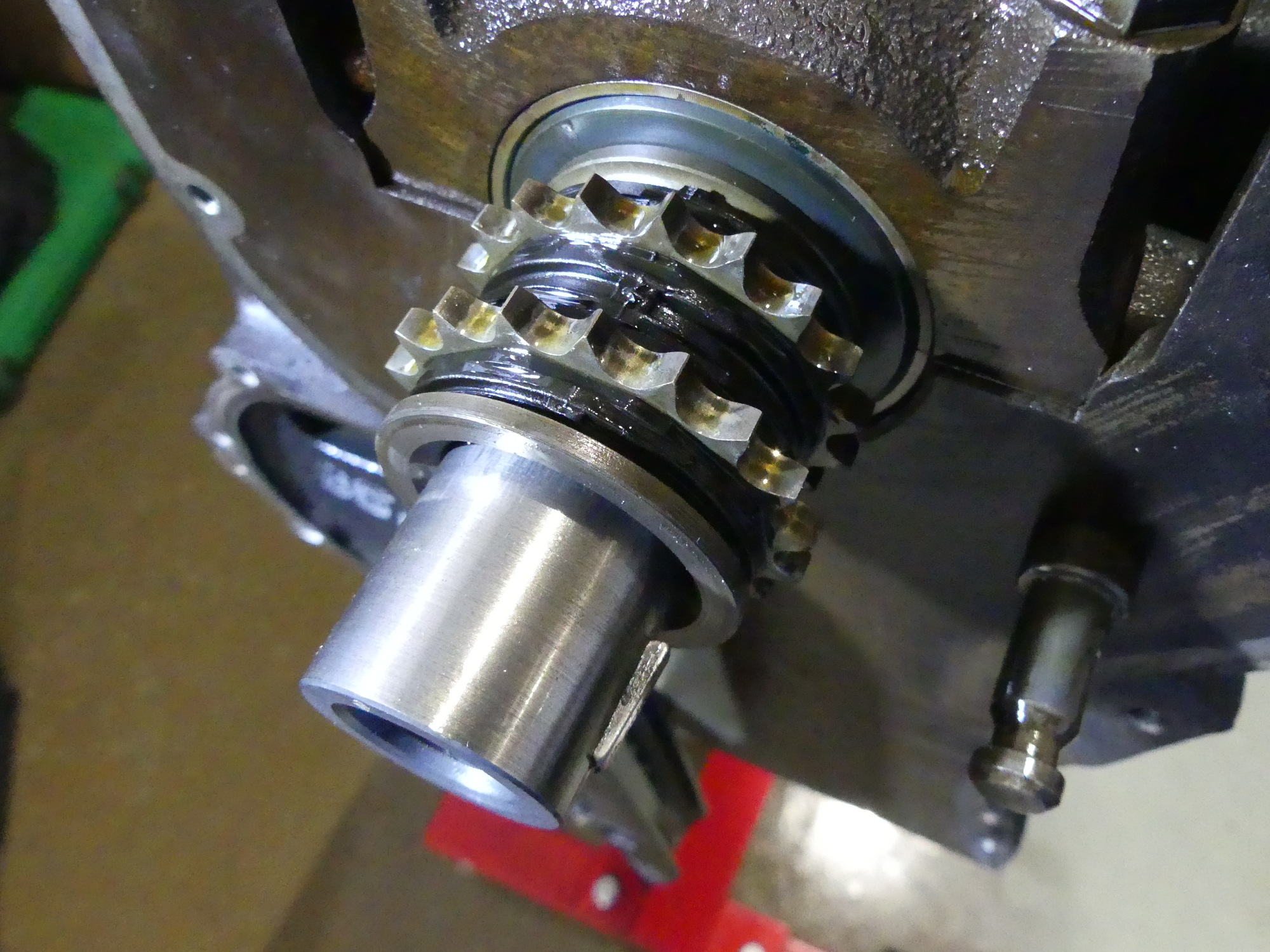 This double chain sprocket mates with the crank in the front of the engine and is responsible for driving both the primary timing chain and the oil pump chain. The rubber (now plastic) on the gear apparently reduces chain noise. Wear is minimal but this sprocket will be replaced. |
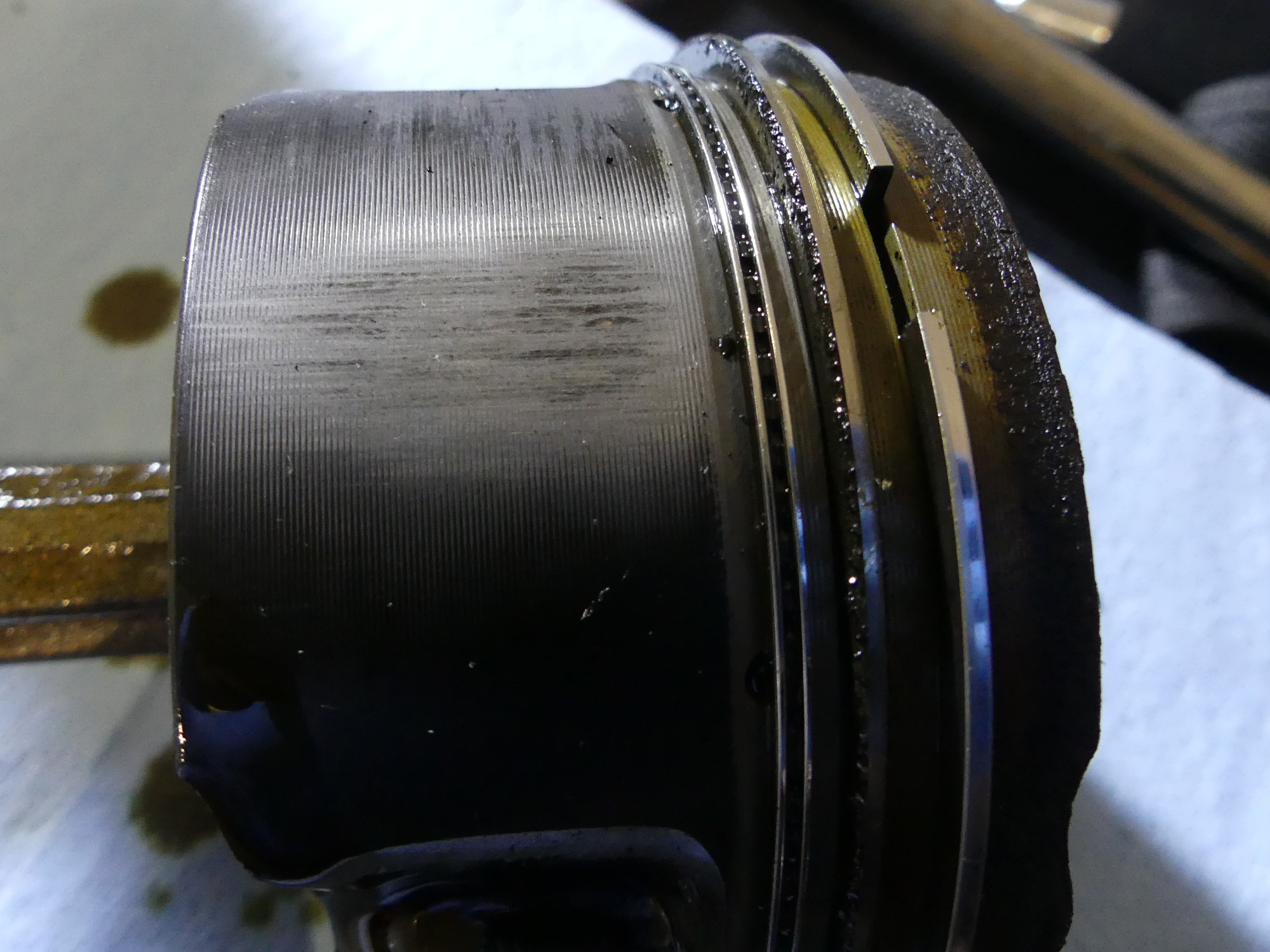 This is the worst of the piston scuffing. It's not pretty but to be expected on an engine that runs such tight piston to cylinder bore clearances (0.8 to 1.5 thou). As these are cast pistons and my replacements are 4032 high silicon forged I'll be running slightly wider clearances (2.5 thou). |
As I needed two hands -- one to hold the stick and the other to hit it with the hammer, I neglected to catch the first piston. It came flying out of the block. Fortunately, I had foresight to position a plastic tub over the engine stand support so the piston didn't suffer any damage but it did cause the tub to fall off the support. I stopped for a moment, knowing that I had to come up with a better solution for the remaining pistons -- and I did. I located a rubber bungie and strapped it around the block such that the rubber extended over the center of the cylinder I was removing. This allowed the piston to move below the deck but prevented it from dropping until I could reach under the block, move the bungie to the side and slide the piston out. I repeated that process with the remaining pistons and left the garage ready to remove the crank tomorrow.
Bottom End Part Analysis
I noticed several paint marks on the crank. At first glance it was difficult to see whether they were white or yellow but I found one of the paint marks in good shape, rubbed it with a towel and stared at it long enough to figure out that it's yellow. That is the first standard grind, which means my crank is the fattest of all the cranks BMW manufactured. This also means that if necessary I could polish the journals and easily bring it into the range of a green bearing, which is the middle-of-the-road thickness. But here's the thing -- the connecting rod journals are in BEAUTIFUL shape. Assuming the mains are in similar shape I won't be forced to do anything to the crank. But I'm getting a bit ahead of myself. I haven't cleaned the journals or really inspected them closely yet.
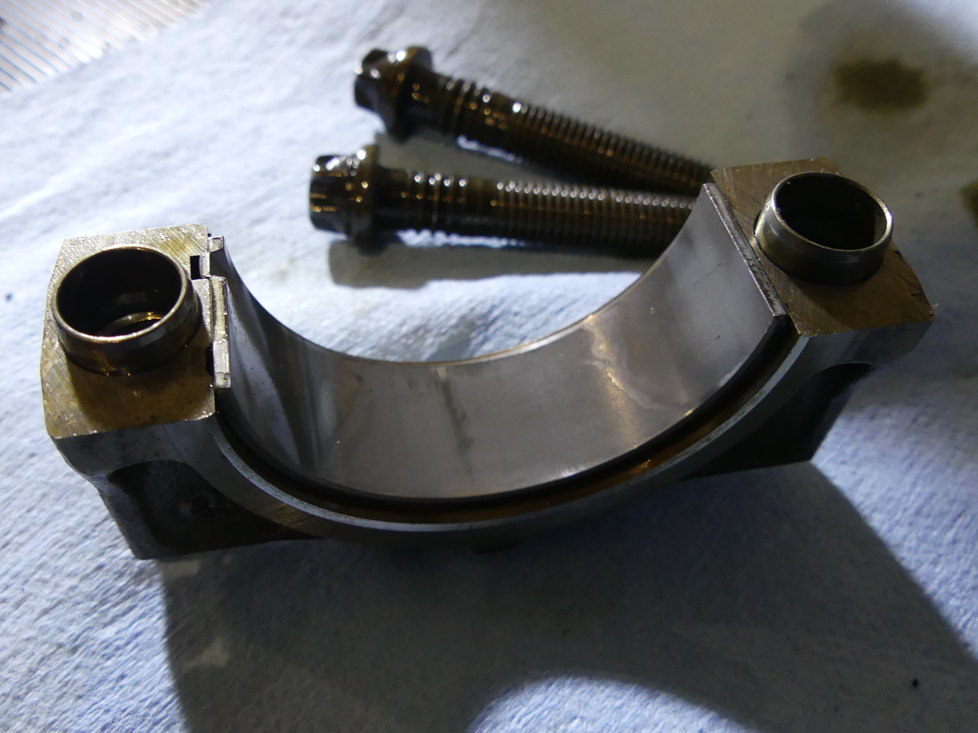 The connecting rod bearing wear on this engine is extremely consistent. This is probably the worst of it. It's gone through the first layer of the bearing and it's a bit tapered, but that's to be expected to some degree. |
 The cylinders were worn enough to create a substantial ridge near the top that prevented the pistons from smoothly exiting the bore. I had to resort to a universal alignment tool (hammer), a block of wood, and this strap to prevent the piston from rocketing out of the cylinder when the rings finally cleared the ridge. |
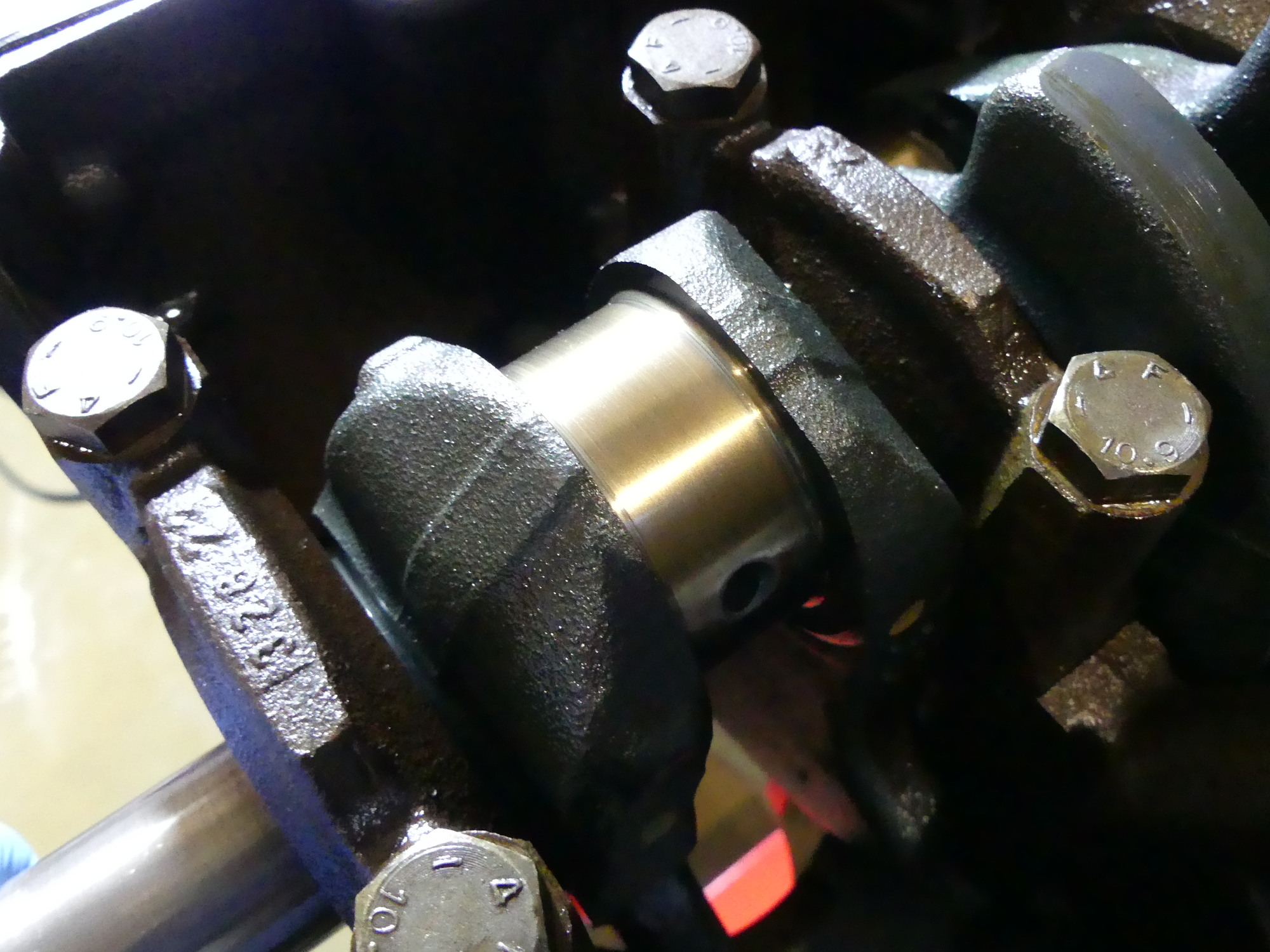 This is pretty typical of the condition of the connecting rod journals. They look damn near brand new. If the mains are in similar shape I don't think I'll need to do anything to the crank but have it cleaned and balance checked. |
The other good news is I now know where the lead was coming from the last 50K miles -- it was indeed the rod bearings (and, I imagine, the mains as well). The even better news is that the wear patterns on all the rod bearings is perfect. Yes, they are worn on the top and bottom through the initial layer, so it's easy to see a dividing line where the wear tapers off, but the key is that the wear is consistent and even across the face of the bearing. This means I am likely to find my journals completely flat and damn near close to original specifications. Seeing the state of the rod bearings I now feel completely justified pulling the engine for overhaul. I could have waited, but had I done so it's quite likely that further wear of the bearings would have exposed harder metals that could have destroyed the crank.
Next Up
Tomorrow I plan to pull the crank, inspect the main bearings, clean up the crank as needed to remove the oil from the journals, and then inspect and measure all the journals. From these measurements I should be able to confirm that the crank is indeed a yellow crank and whether any of the journals are worn unevenly. If I do find uneven wear I should be able to calculate the bearing types I'll need for those special cases. But if I don't polish the crank and the wear is consistent across journals as I imagine it will be, I should be able to throw in a new set of yellow bearings and effectively restore the crank to like-new specs.