


Thursday, August 3, 2017
Crank Pulled and Block Cleaned
I didn't get quite as far as I hoped today, but I did manage to do several things essential to meet my goal to deliver the block and various parts to the machinist on Monday. I also managed to assemble and test some of the measurement tools I'll use during assembly to validate the machinist's work and ensure I maintain clearances within specifications.
 Here is a closeup of the main bearing cap showing the number punched into it. The caps are marked beginning with one closest to the front of the block, followed by 2, 3, 4, and 5. The thrust bearing and the last cap at the rear of the engine are not labeled. |
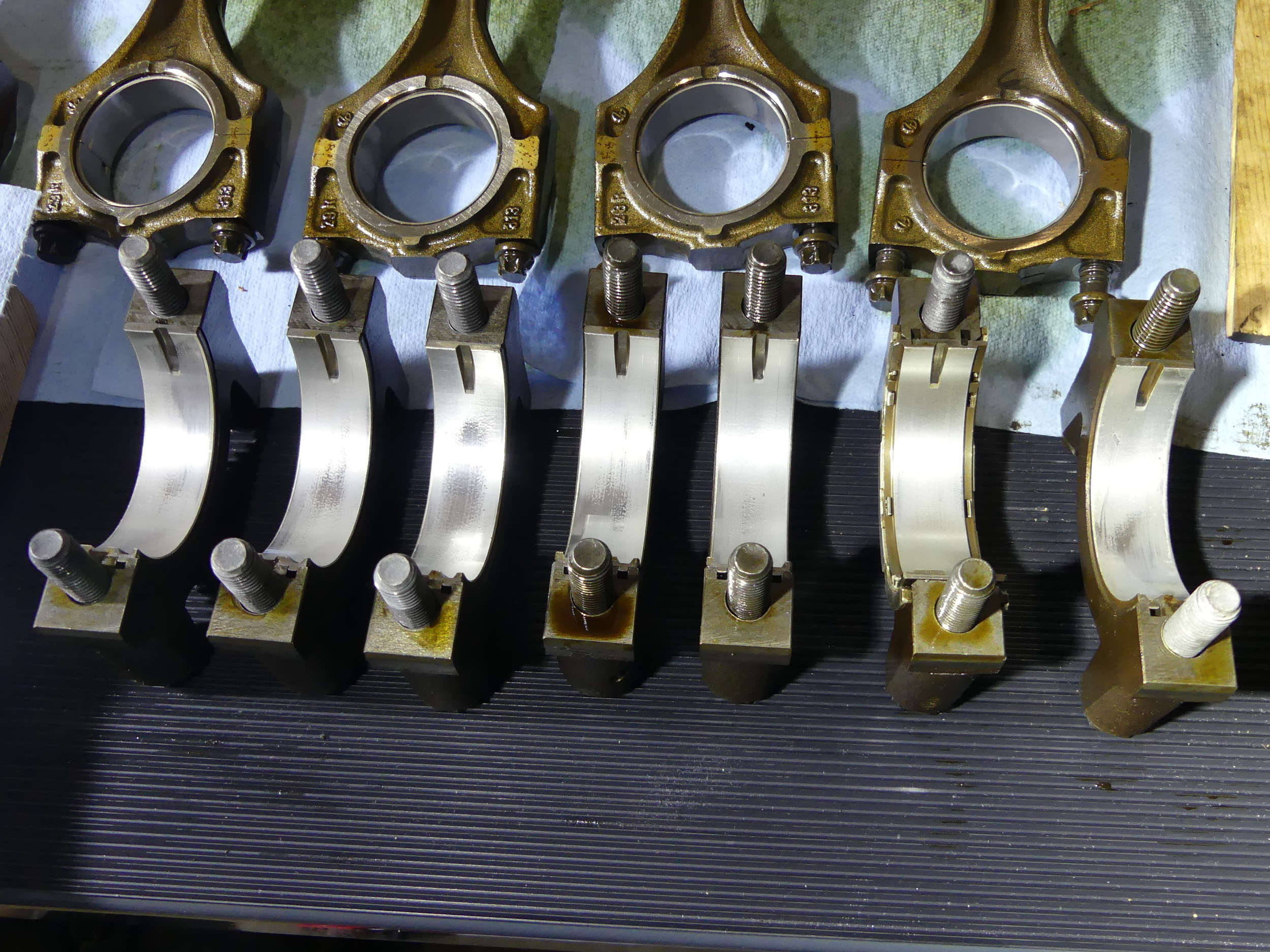 The main bearing caps with original bearings installed. These are in outstanding condition for the mileage, though they are starting to show a bit of wear through the surface layers. Nothing unexpected for nearly 270K on the clock. I attribute the condition of these bearings to routine oil changes. |
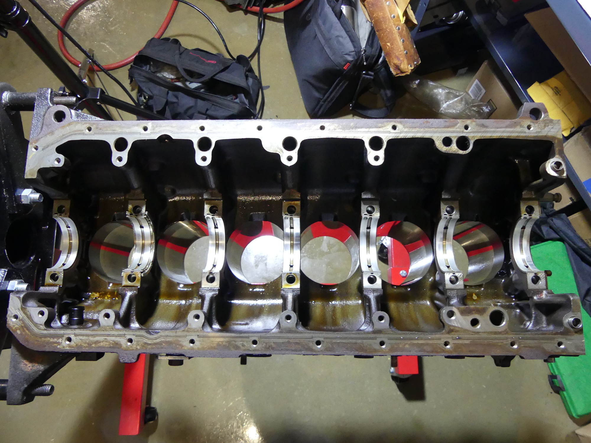 Just a top down picture of the block with the crank removed. If you're used to looking at an M54 you might wonder where the hell the oil squirters are hiding. I wondered that too...until I found them hiding under the bearing shells. |
First I used my IR titanium impact wrench (boy do I love that thing) to remove the main caps. As expected, all of the bearing caps came off easily with the exception of the thrust bearing, which required more of a side to side rocking motion rather than the fore-aft push/pull technique used to remove the other caps.
Removal of the caps revealed some wear on the main bearings, but nothing like that I found on the connecting rods. The thrust bearing was also in surprisingly good shape aside from a couple spots on one side where the bearing surface had clearly been worn through at least the first layer. The distinguishing characteristic of these wear areas was a color I can only describe as a lighter shade of gray. At this point I think it's safe to say that the majority of the lead reported via the oil analysis was coming from the rod bearings. An inspection of the crank revealed main journals in like-new condition, which means that the crank will only require a professional cleaning and a balance check.
After the crank was removed I took a closer look at the block. My initial reaction was "where the hell are the oil squirters?" I was fully expecting to find the squirters individually mounted to the block casting, much as they are in the M54, but closer inspection revealed they are inserted in a port machined at an offset in the main bearing ledges. More interesting is that the squirters are not press fit or secured in any way -- they free float in the hole milled for them.
To remove the squirters I just reached around the bearing ledge and pushed up on the squirter aperture. The squirter body appears to be made of brass as it was not responsive to my magnet tool. As expected the squirter is equipped with a check ball. I carefully blew some air through them to clear them of any debris but I'll likely likely soak them in mineral spirits, blow them out again, and ensure the check ball is operational before I reinstall them. I briefly considered replacing them for good measure but they are about $20 each with my discount. To rich for my blood, particularly if there is nothing obvious wrong with them.
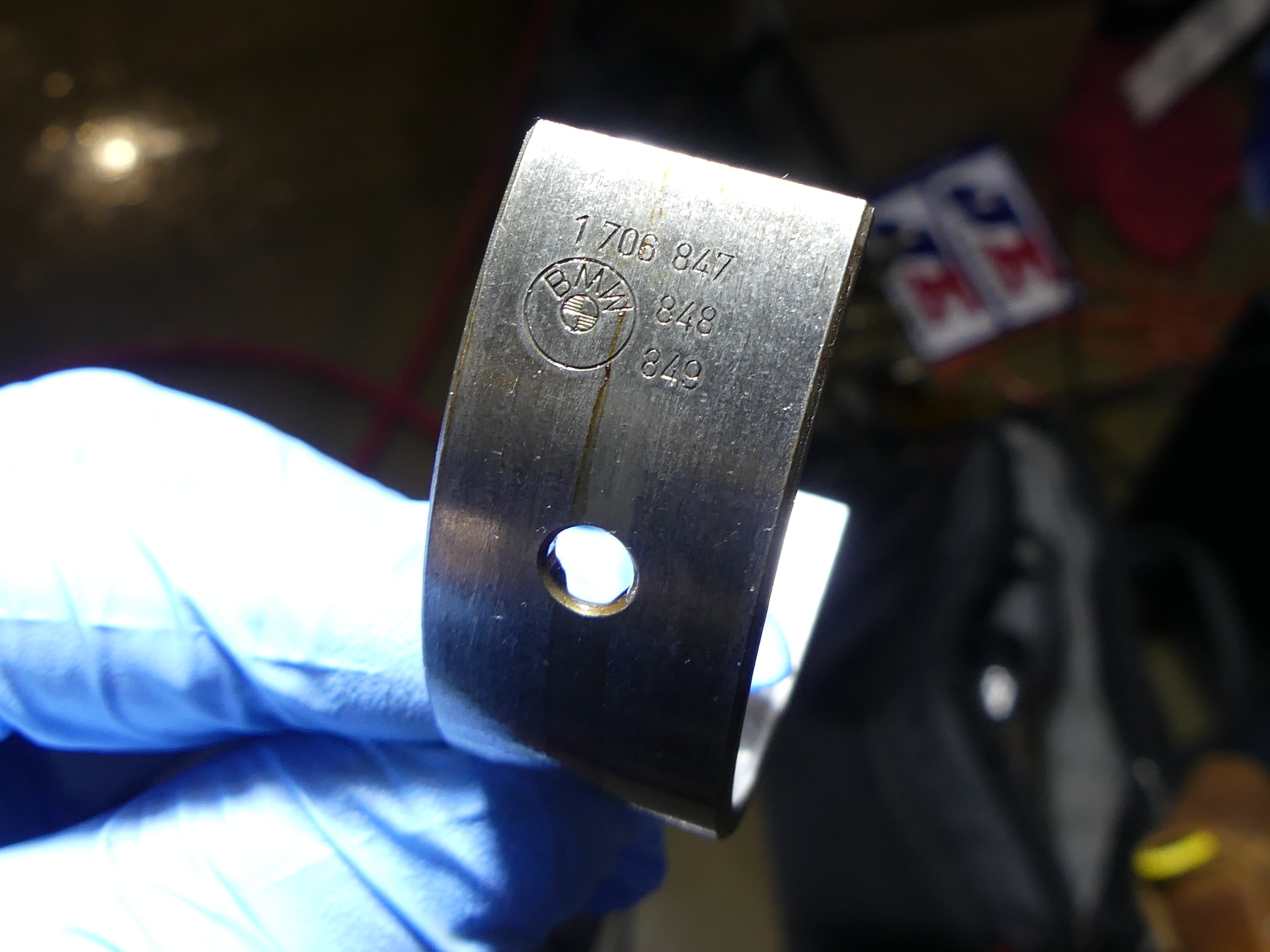 A closeup of the rear of the main bearing shell. Those numbers are of course the BMW part numbers for the shell, but unfortunately it is not possible to use these to determine the specific bearing type installed. The 847 bearing is a yellow, 848 is a green and 849 is a white. |
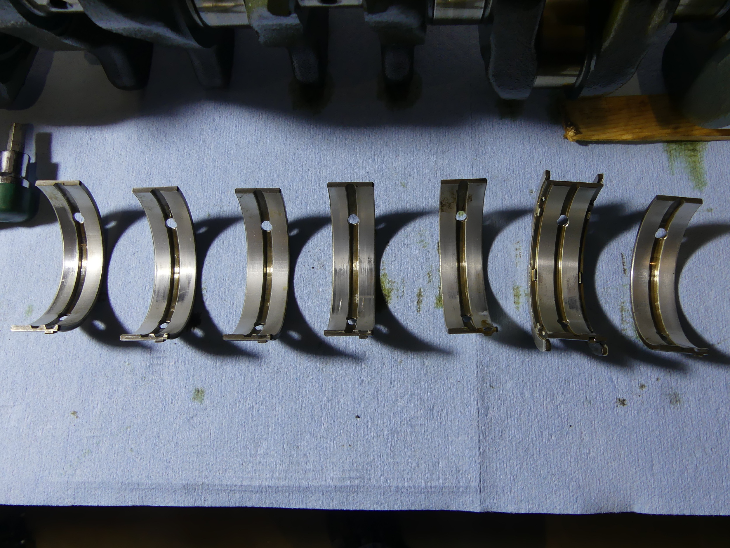 A closeup of the block side (upper) main bearing shells. These again show modest wear, with the first and fourth shells showing the worst of it. FYI, each of the regular bearing shells are worth $22 (my cost) and the thrust bearing is worth $45. Multiply by two to arrive at the cost for a complete set. |
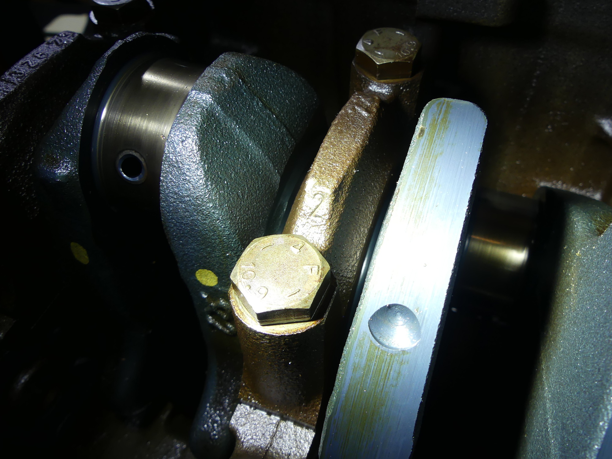
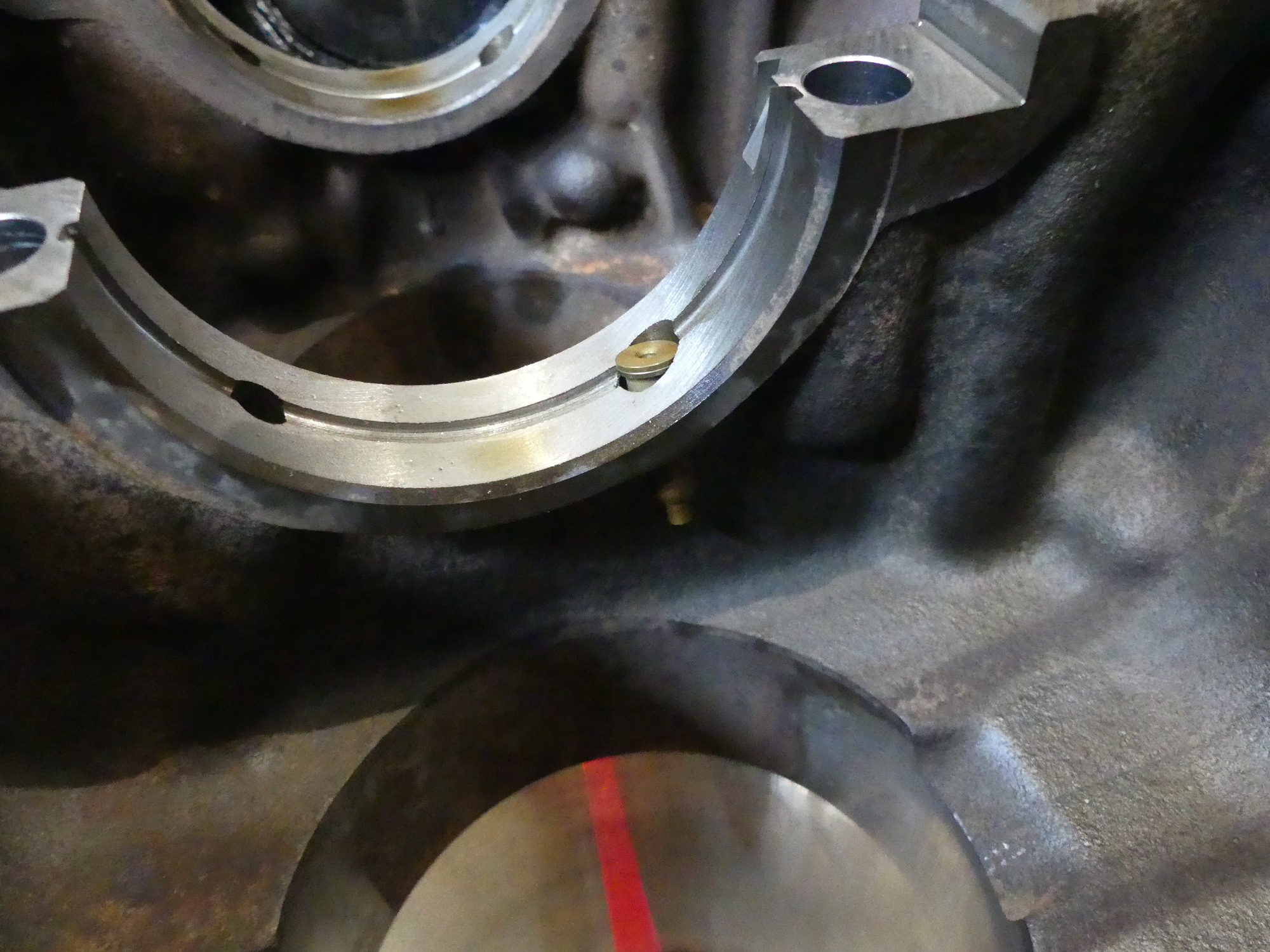 Where's Waldo? Oh, there he is. Here I'm showing the squirter pushed upward slightly. Normally that is pushed down a bit more so it sits well below the base of the bearing shell. Oil feels through that slot in the bearing ledge from the gallery (hole) on the left. Oil then bathes the bottom of the piston, helping to cool it. |
Preliminary Cylinder Measurements
I then brought the block outside for another cleaning, this time using my spray wand to dispense mineral spirits. The goal here was to remove a bulk of the remaining oil and grease on the block, and specifically the cylinder walls, so that I could do some preliminary measurements.
It took me some time to figure out how to assemble my digital bore gauge. It turns out that the gauge has a very small amount of travel, which must be adjusted to the desired bore size with one of several extensions provided in the kit and fine-tuned with some osmaller adjustment rings. With the unit assembled I turned my attention to my 3-4" inch micrometer. As bore gauges measure relative distance they need an absolute reference, which I provided with my 3-4" micrometer. For convenience I mounted the micrometer frame in my vise equipped with soft jaws and then used the 3" standard provided in the kit to zero the tool. With the micrometer now calibrated I removed the standard and then rotated the thimble until I saw 84.000mm. Finally, using one hand to hold the head of the bore gauge and another to keep the measurement end aligned between the anvil and spindle of the micrometer, I pressed the "origin" button on the bore gauge. This zeros the bore gauge and establishes its reference dimension.
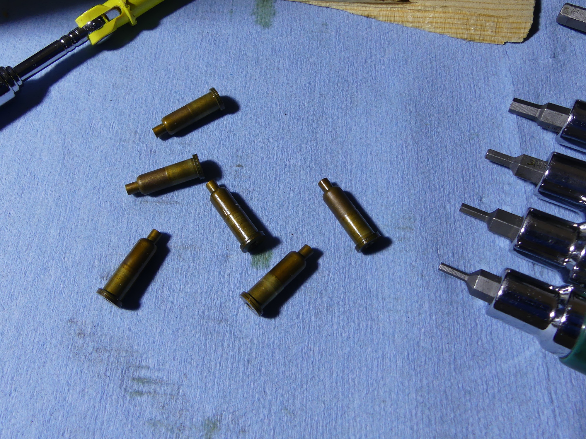 Behold $120 in oil squirters. Well, they were cheaper in 1998 but that's the 2017 replacement cost. So far all the check balls appear to be working correctly. I blew them out today but expect to soak them in mineral spirits and clean them out again before reinstalling them. |
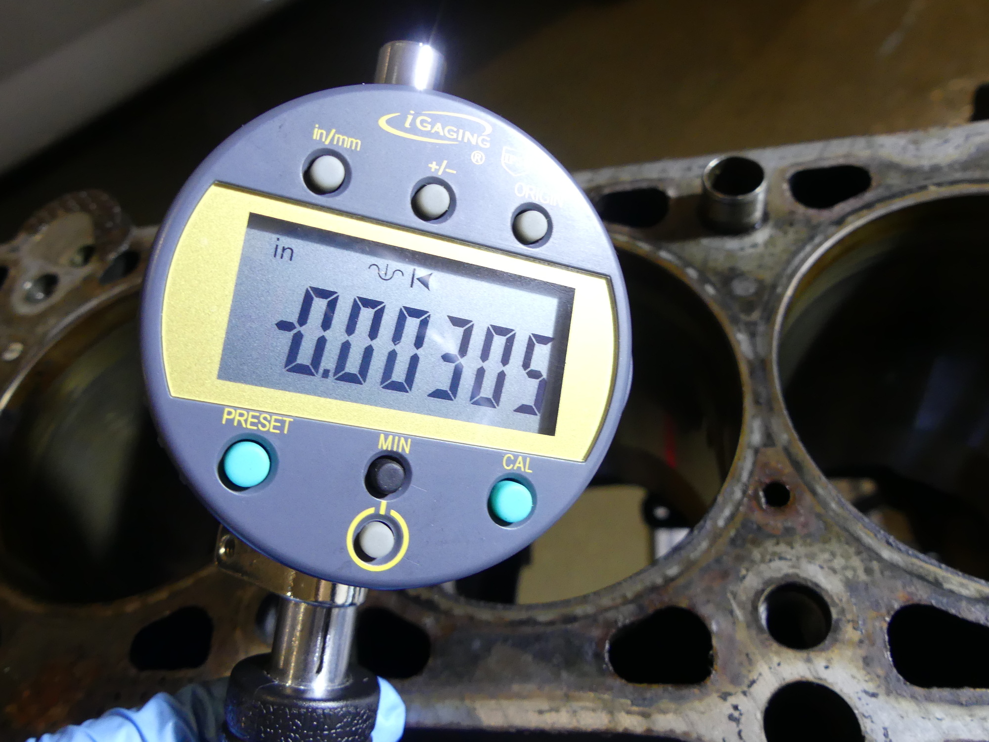 Digital bore gauges are so superior to analog gauges it's not funny. The "Min" function makes taking accurate, repeatable measurements quick and easy. No staring at the stupid dial, throwing it back and forth looking for the reversal point. Rock it slowly twice and the minimum dimension (square to the bore) becomes fixed on the display. |
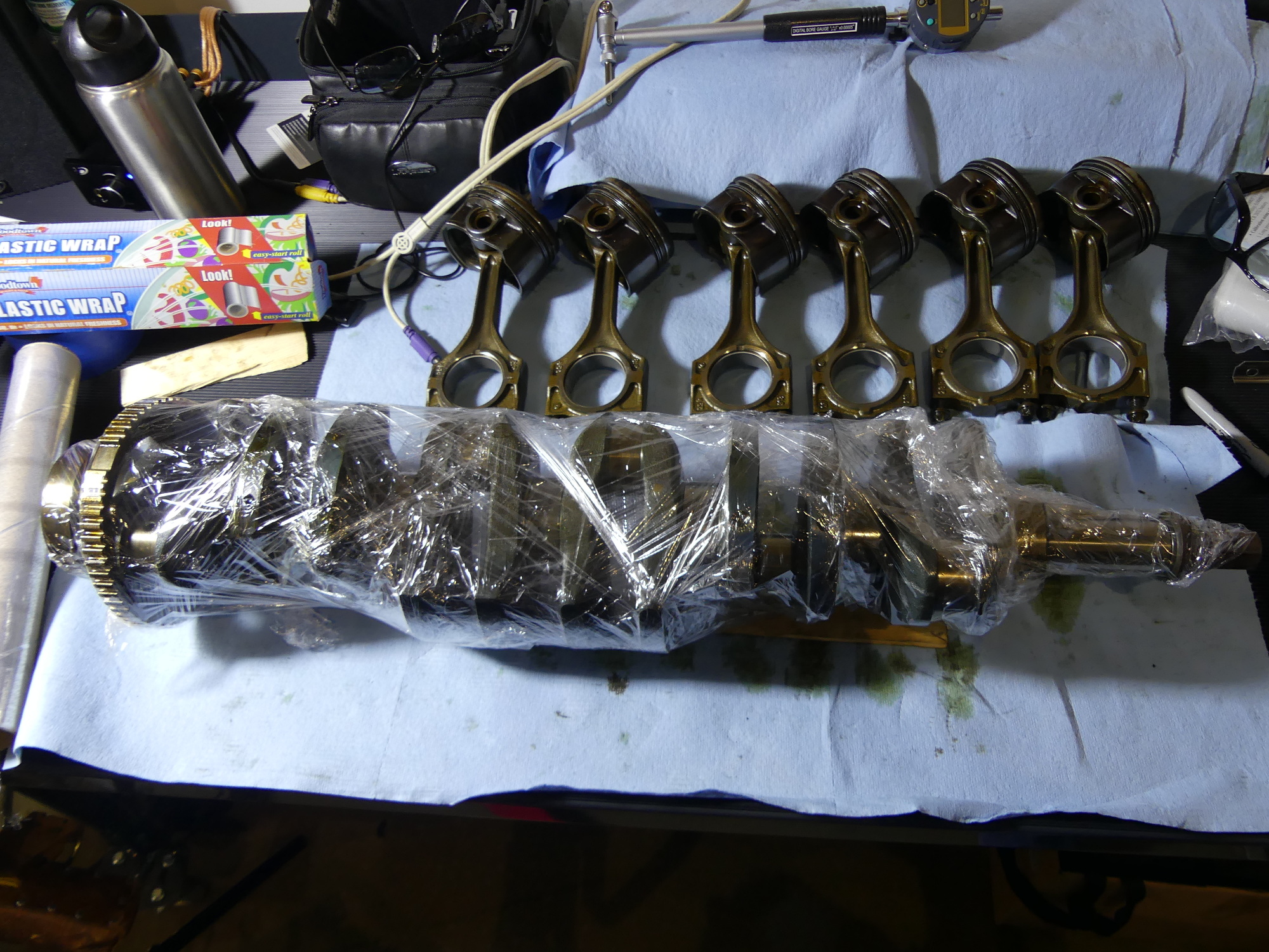 I decided that I would mic the crank after it returns from my machinist, professionally cleaned and balanced. The oil film on the crank will protect it in the meantime, and the plastic wrap will make it easy to transport without getting dirty (my hands or the crank itself). |
With the bore gauge set to an 84.0mm reference I took some sample measurements in the cylinders. This is where the digital bore gauge proved its worth -- I inserted the gauge into the upper portion of the first cylinder in live measurement mode, tilted the gauge to one side to achieve a "maximum" measurement, and then pressed the "Min" button to enter minimum measurement mode. Once in that mode, the minimum measurement is obtained by slowly rocking the gauge handle 20 degrees either side of vertical. Each measurement is precise, repeatable, and does not require either looking at the gauge while rocking the tool or leaving the gauge in the bore to obtain the measurement as the measurement is permanently recorded until cleared (or the mode is switched back to live measurements). As a result, it took only about a minute to measure all of the cylinders -- twice in the same location to confirm the original measurement. The end result? Measured at the top of the cylinder in the X direction (across the block) all of my cylinders were between 2.5 and 3.0 thou oversize, with the majority being 3.0 thou. This means the average bore is 3.31009 inches or 84.076mm.
Next Up
Tomorrow I plan to package all of the parts I need to send to the machinist on Monday. I also need to put the finishing touches on a parts order I'll need to begin work on the vehicle fuel system next week.