


Wednesday, October 11, 2017
Cams Installed With BMW Special Tool
When I got home from the garage Sunday evening I composed a parts list including the needed helical shaft and emailed it to my parts rep. Monday morning I received an email indicating that the everything I needed was available in the US and could be delivered in a couple days so I decided to order the new shaft. This will leave the original shaft mated to my cams, which I plan to sell when the project is complete.
This morning I went to the dealer to pick up the parts and speak to my tech about installing the helical shaft in the intake cam as well as borrowing the special cam installation tool. He couldn't install the shaft at that moment but suggested I could leave it with him and he would text me when it was done. I said that was fine, but it would naturally require me to keep the tool a bit longer. He smiled and said "don't worry about it...that tool just gathers dust these days, as the new engines use a different tool". He showed me the new tool, which looks like a thick machined C-clamp. Apparently one is required per bearing cap. I didn't bother to ask how they are synchronized. Probably quarter turns of the wrench. Ha!
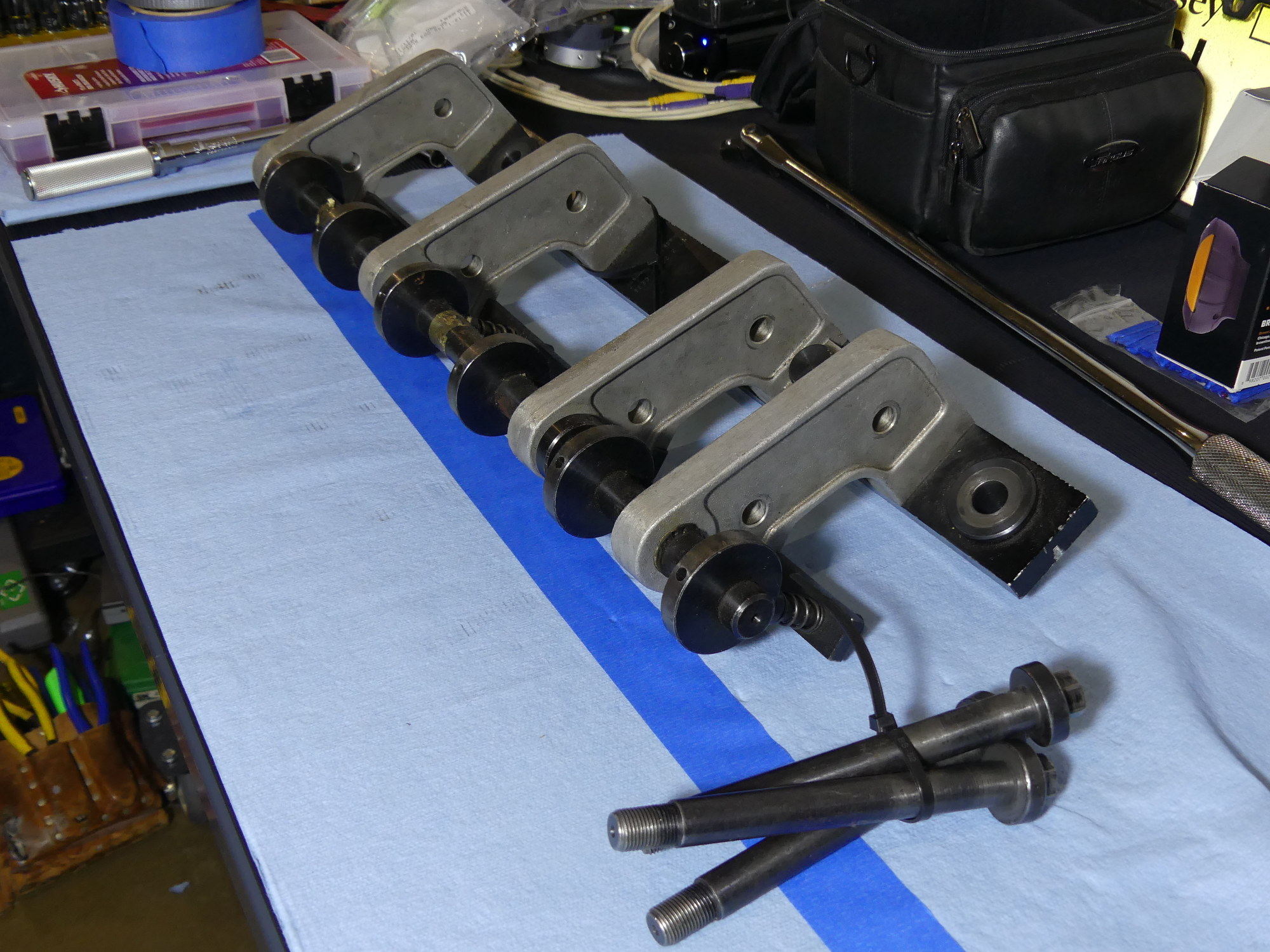 The professional relationship I've cultivated with my technician over the last 20 years has certain perks. He loaned me the dealership's special tool to install my cams. NOTE: I do not own this tool and cannot acquire it for you so please don't ask. |
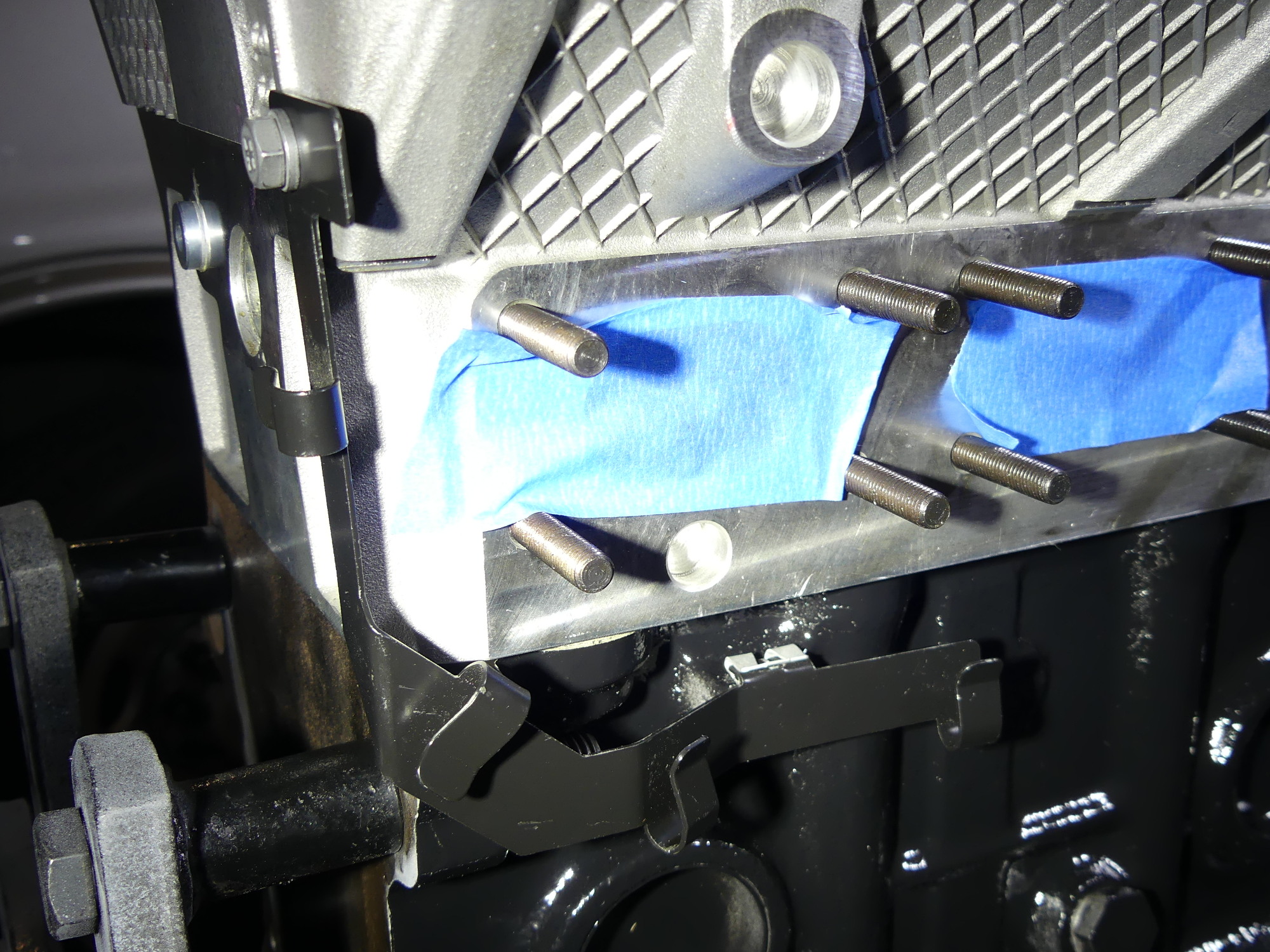
 Quickly fitted to the block using three bolts that are secured to the threaded spark plug bores, the tool is comprised of two sections that work for 4 and 6 cylinder cars. Note that the two parts aren't synchronized in this picture. I fixed that before using it. |
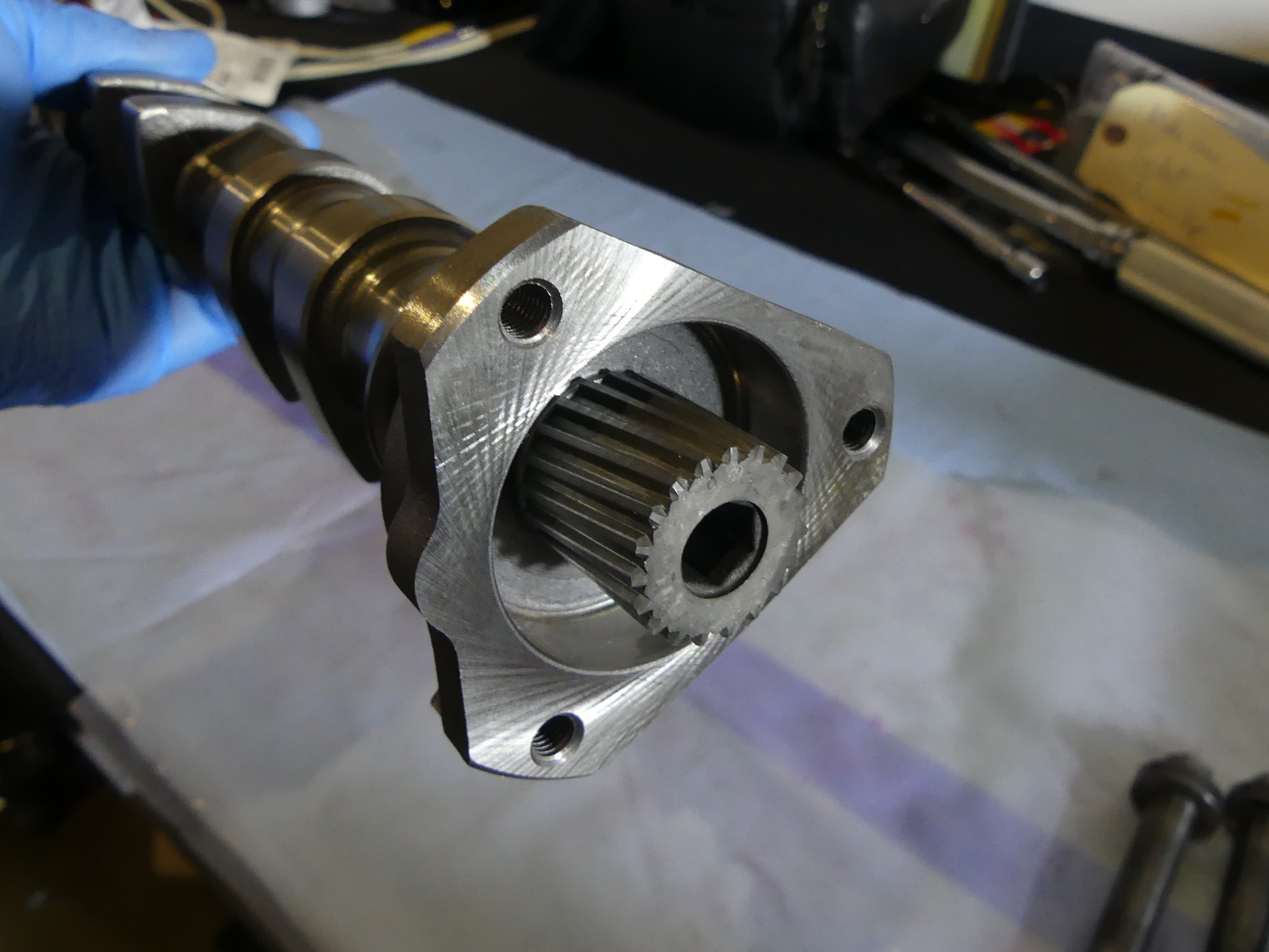 Mostly because I was afraid my unstable vise would not be able to handle the torque required to mate the helical shaft with the new cam I gave this job to my technician. So now I have a new shaft to go along with my new cam. |
Back at the shop I quickly attached the special tool to the head and used an open-end wrench to rotate the tool's cam as required to carefully drive all of the bearing caps except A1 down to meet the carrier. I was careful to shake each bearing cap a bit as I did this, just to ensure that they were not hung up. If you're wondering why A1 was left off, that is a TIS requirement. The A1 and E1 caps are unique in that they integrate thrust bearing surfaces which are designed to closely mate with the corresponding surfaces on the cam. The clearances are so close, in fact, that if the cam is not perfectly aligned with respect to the carrier bore axis, it will bind up on the A1/E1 cap. If this binding occurs while the cam is being pushed down with considerable force damage to the thrust bearing surfaces may occur or, in an extreme case, the cam may break.
With the A2 through A7 caps firmly pressed down onto the carrier I then installed the nuts hand tight before using my 1/4" drive torque wrench to apply a fixing torque of 50 inch pounds. This step is not specified by the TIS, but I felt it was necessary because the tool tended to get in the way of swinging the wrench. My goal was to firmly seat the nuts so I could remove the tool, install the A1 cap and nuts, and then apply the final torque of 14Nm (10 ft*lbs, or 124 inch pounds) to all nuts.
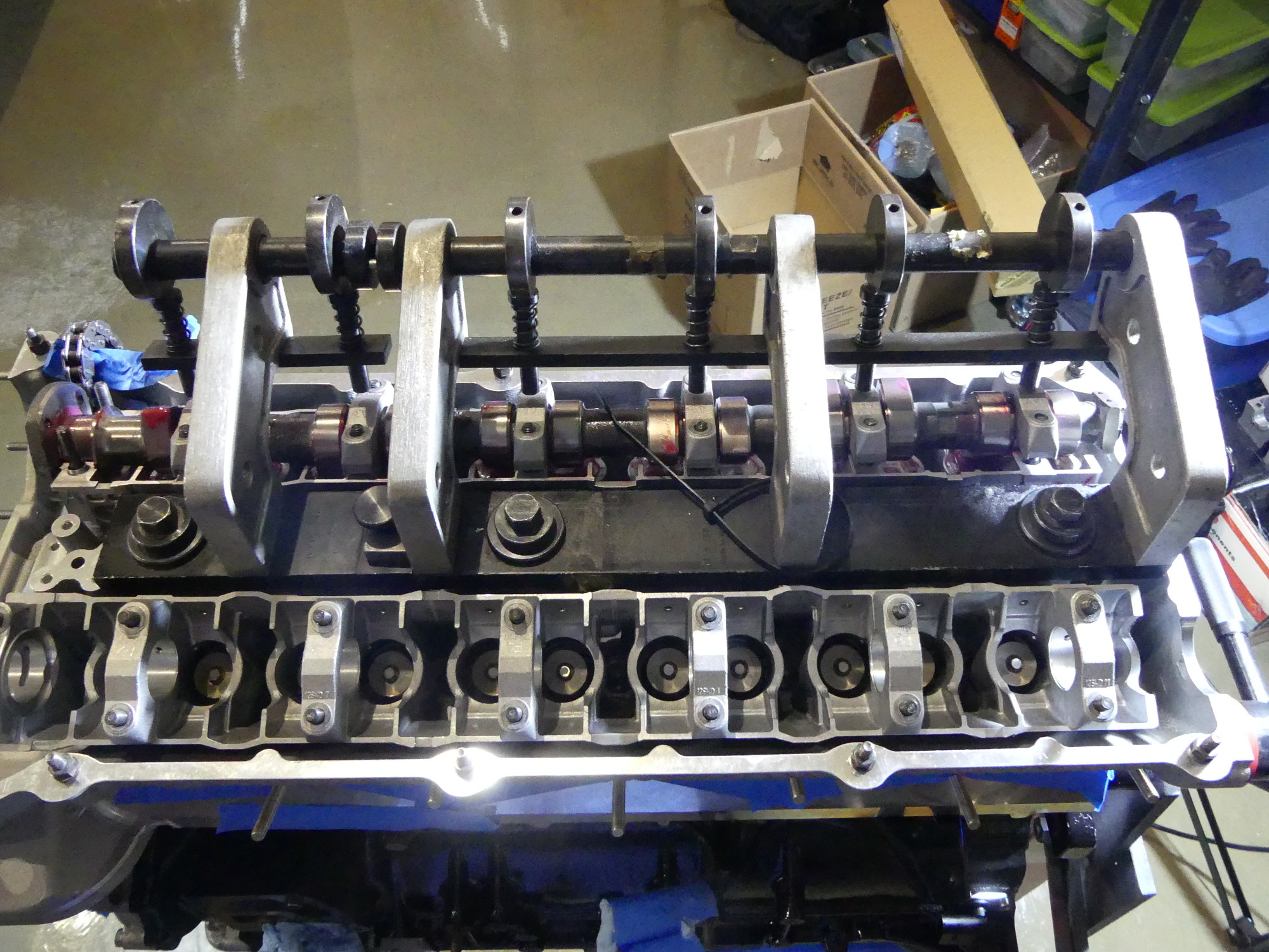
 A perspective shot showing both cams installed and locked at Cylinder 1 TDC with the locking blocks. I'll refresh the cam lobes with assembly lube just before I install the valve cover. The VANOS unit is only installed temporarily. |
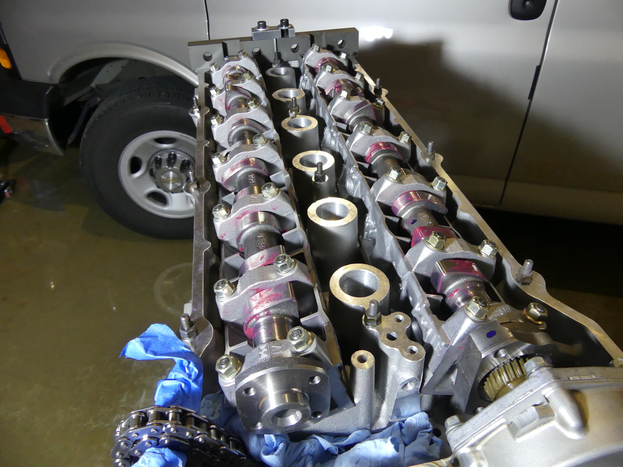
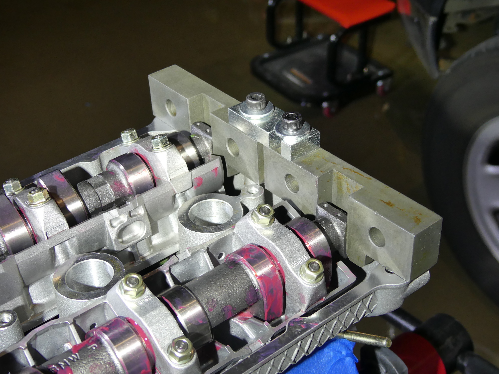 A closeup of the CAM locking blocks. These work in conjunction with the square portion of the cams to keep them precisely positioned. Now that the top of the engine is locked at Cylinder 1 TDC, I have to lock the bottom at TDC before I can time the engine. |
 With the cams installed, the imminent threat to project completion has been eliminated and we are back in peacetime operations -- in other words Project Condition (ProCon) Green. :) |
Later in the day my tech let me know the intake cam was ready so I went over to pick it up. Returning to the garage I duplicated the above effort for the intake cam and by the end of the day had both cams installed. In no more than a couple of minutes I rotated both cams into the TDC position and installed the cam locking blocks. The cams are now configured for the engine timing process and we are now back at ProCon Green. :)
Water Pump and Miscellaneous Parts
In my continuing effort to close up as many holes in the engine as possible as to avoid contamination of any sort, I decided to install the water pump. Normally the o-ring is supposed to be lubricated with coolant but I didn't want to go to my garage to get some so instead I applied an almost imperceptible coat of silicone paste lube on the o-ring before sending it home. To hold the pump to the timing cover I torqued the four 10mm nuts to 10Nm (88 inch pounds) again using my 1/4" drive torque wrench.
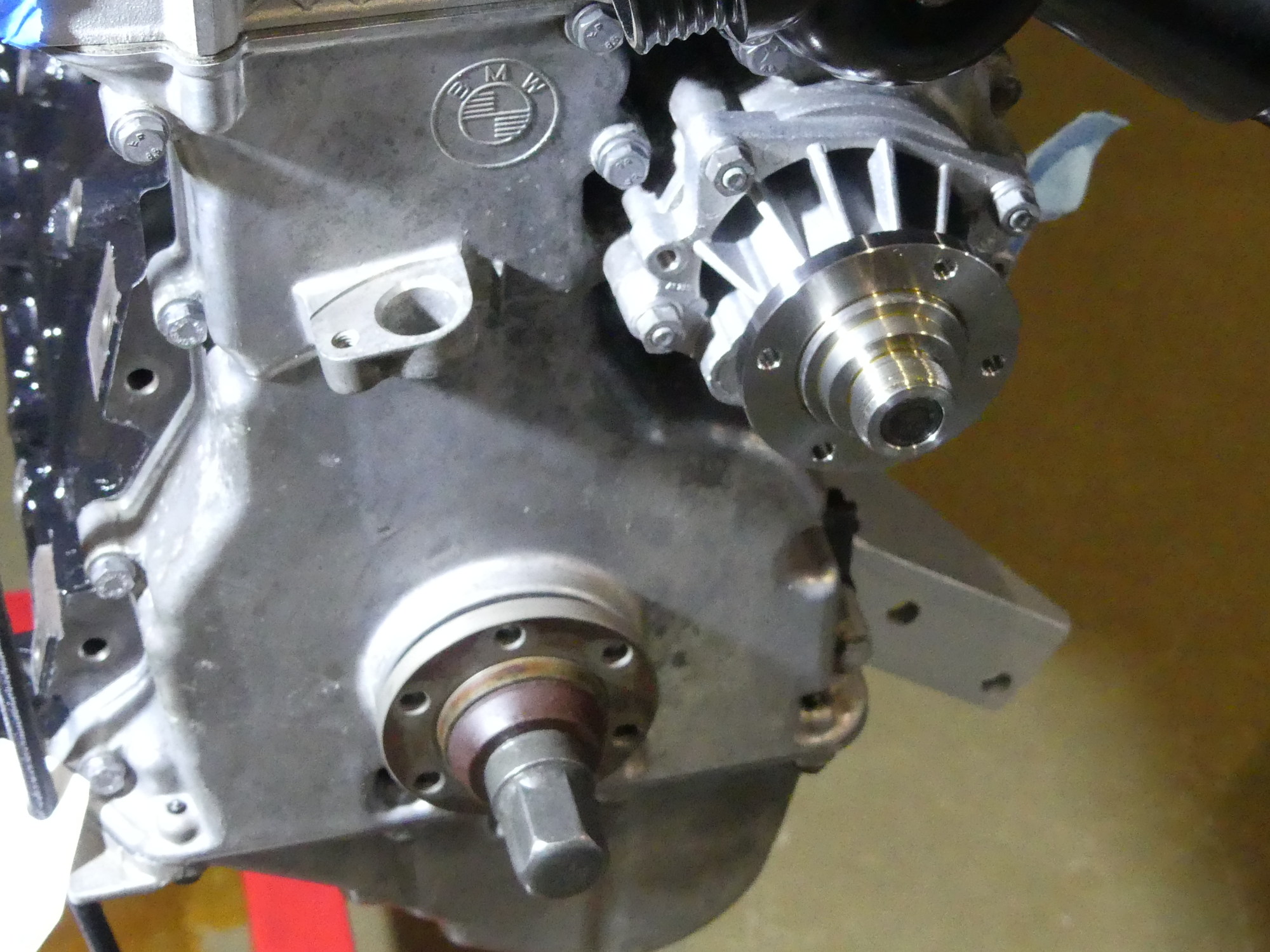 One of the easier things to install on this engine is the water pump. The nuts were reused, mostly because they were still in good shape, a characteristic I attribute to the fact that they were ZnNi plated. |
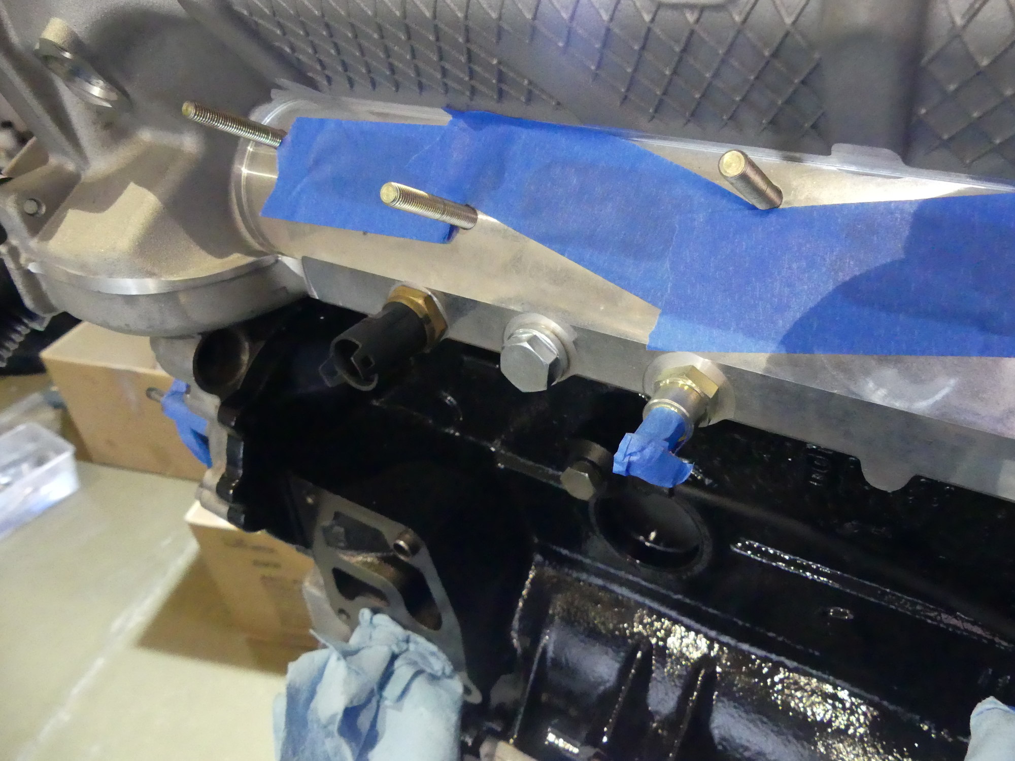 From left to right, the reused temperature sensor, closeout plug, and coolant connector. The sensor was hand tightened until the sealing plug began to compress, while the others were torqued to 22Nm (15 ft*lbs). |
 With the head firmly attached to the block I decided to install the new O2 sensor wire support bracket. This fastens to the head with a ZnNi plated bolt, while the other side clips to the block with a Zn plated clip. |
I then realized that in order to time the engine I would need disconnect it from the stand as required to install the flex plate and the TDC lock pin. This process would require a couple of lifting points so lacking any other options I resolved to install the lift bracket on the front of the head. I quickly realized this would in turn require temporary installation of both the VANOS unit and thermostat. Unfortunately, as I was tightening the thermostat housing I heard a disconcerting "crack". A close inspection revealed a crack near one of the mounting flanges. I'm not sure why or how this happened, as I was tightening each bolt down gradually in sequence and this isn't the first time I've done this. Fortunately, I have a second thermostat housing on hand and will be able to install it later. In the meantime I marked the housing with a paint marker to remind me that it needs to be changed.
Near the front of the head, on the intake side, are three threaded holes. The one closest to the front of the block is intended for what I believe is a coolant temperature sensor. I saw nothing wrong with the sensor so I decided to reuse it but doing so did require the installation of a new aluminum sealing washer. The second hole was blocked off on my engine but Autohead failed to transfer the plug from my old head or include a new one with my new head, so I had to buy a new plug and install it today. The last hole is intended for a barbed coolant connector. I managed to remove the original connector before sending the head out so I could have reused it but it looked a bit crusty so I bought another one along with the required aluminum sealing washer for a few dollars. I couldn't find any torque specs for these parts so I secured the temperature sensor by feel and the other parts to 22Nm or 15 ft*lbs. This is probably a bit lower than required but better safe than sorry.
Next Up
Over the next couple of days I'll time the engine, permanently install the VANOS, new thermostat housing, oil filter housing, coolant pipes, valve cover and, finally, the coils. That should wrap up the engine build in prep for a delivery to my technician early next week.