


Thursday, October 12, 2017
Timing the M52
Today I timed the engine, a process that culminated with the installation of the VANOS.
The most frustrating part of this work had to do with the fact that the flywheel is required to lock the bottom end at TDC for the timing process and yet I could not install the flywheel with engine mounted to the stand due to a lack of clearance with the stand mounting bolts. Another centimeter or two would have worked wonders. So ultimately I lifted the engine with the shop crane, removed the engine stand mounting plate, installed the flywheel with a couple bolts, and used it to rotate the crank back to cylinder #1 TDC while I watched the TDC ruler I inserted in the #1 cylinder spark plug hole. Once the hole in the flywheel reached the TDC locking pin I pushed the pin through it.
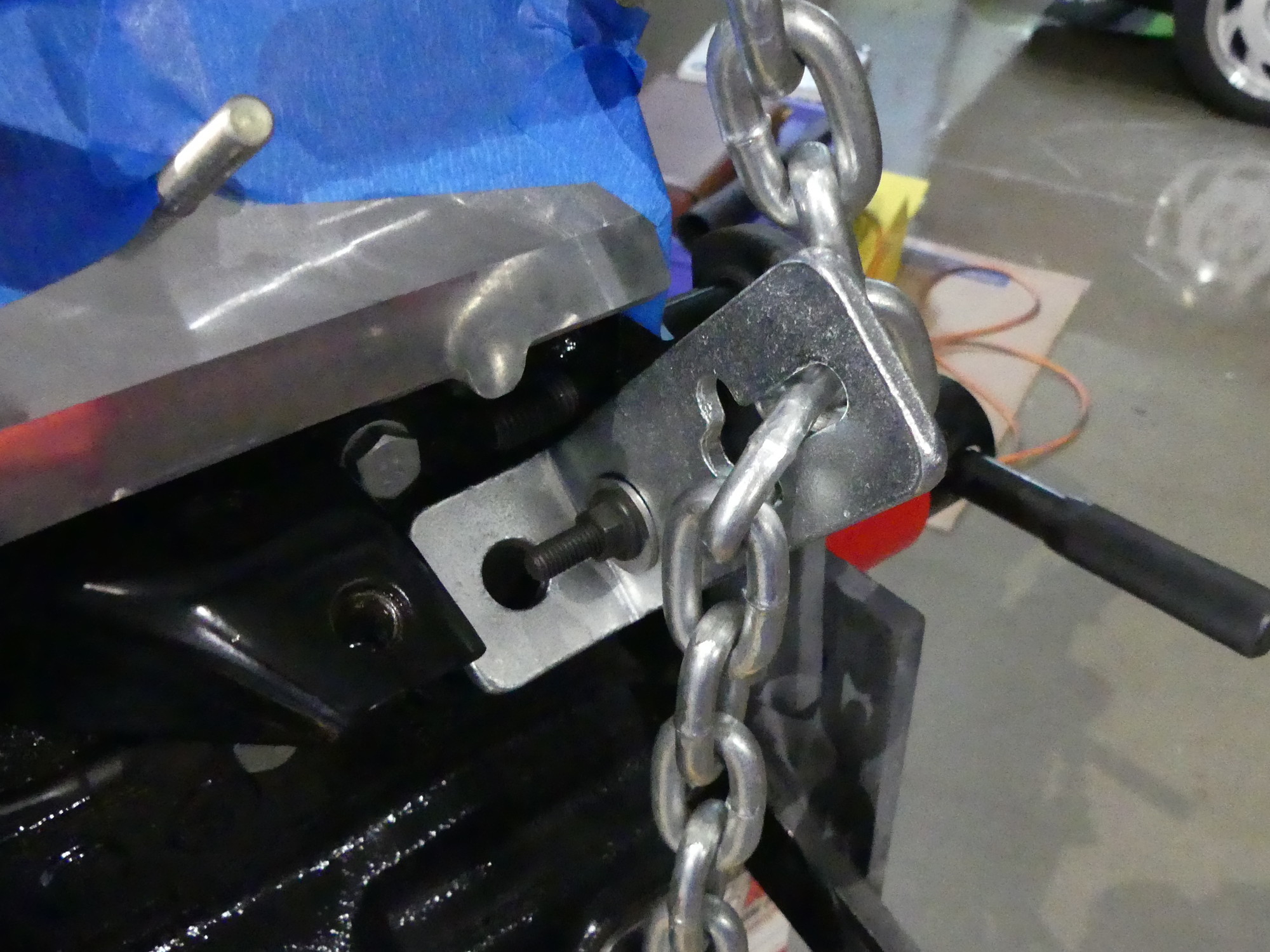 A closeup of the rear lift point. This L bracket came in handy, in that it prevented the chain from grinding against the head. I tightened the bolt until the L bracket was tight to the block. |
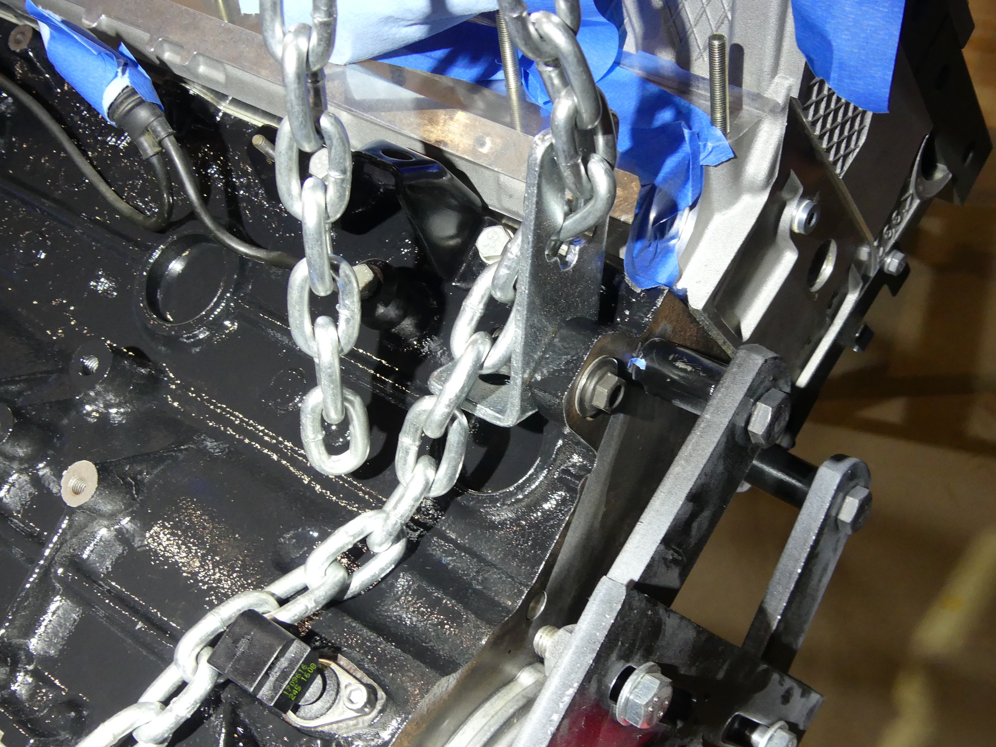 With the L bracket fastened to the block it was a simple matter of attaching the chain and lifting the engine slowly and adjusting the load leveler to release all the load on the stand. |
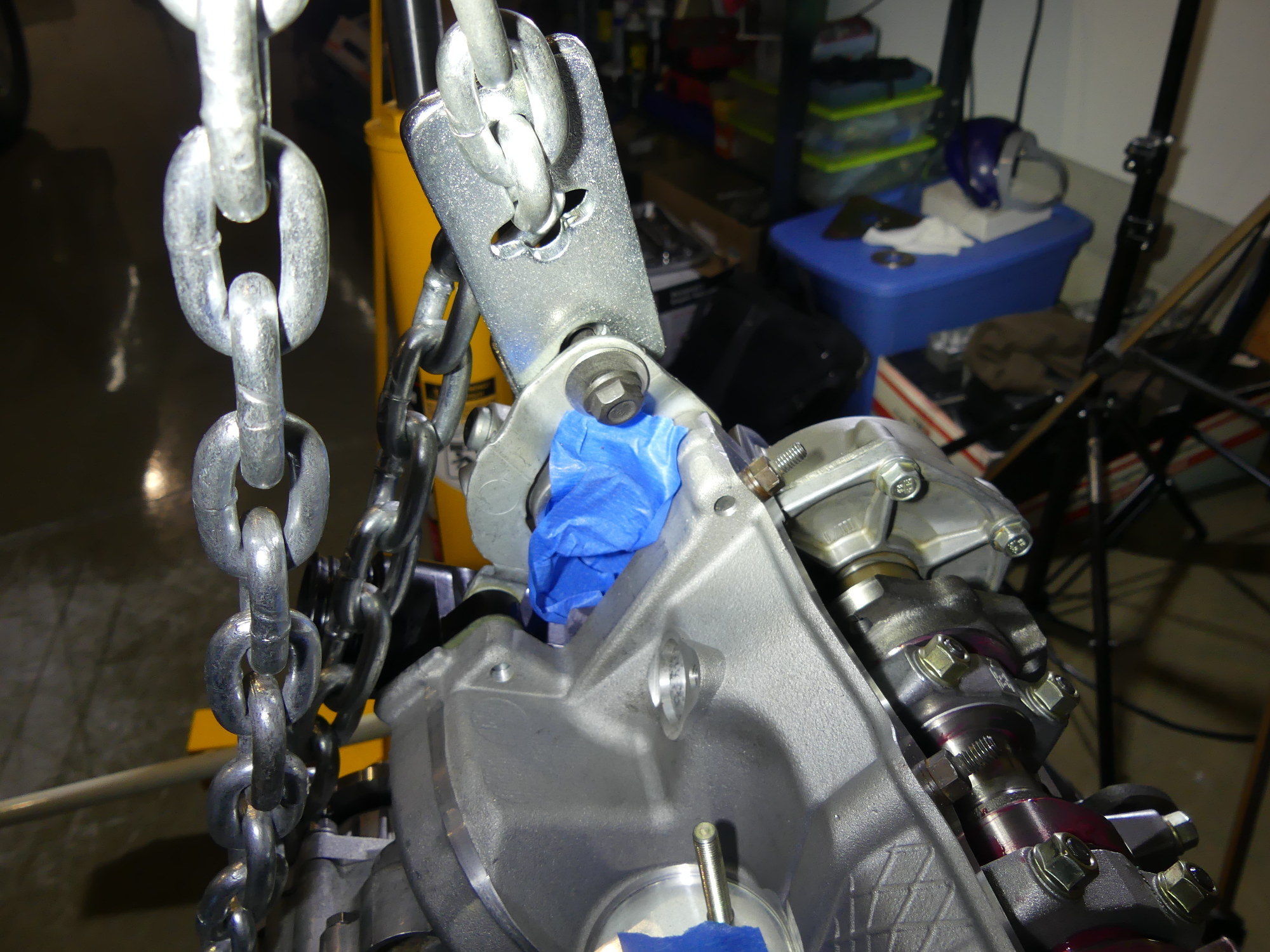 When preparing the front lift point I had to leave the L bracket loose because the bolts were not completely threaded but this worked out well enough and served to reduce interference with the VANOS housing. |
I took a close look at the locking pin and found that it was slightly canted. I ultimately determined this was due to the fact that the pin was a touch too small for the bore milled in the block. I noticed the crank would rotate a couple degrees in either direction despite the TDC pin being installed. For this reason I took extra care to split the difference. This ensured that the pin was not canted and the bottom end was set to the TDC position as precisely as possible. Afterward I verified that the TDC ruler showed cylinder 1 at TDC.
I tried adding washers to the engine stand mounting plate bolts to get the clearance I needed but the bolts still hit the flywheel. As I knew I had a lot more work to do on the engine and wasn't about to trust the cheap shop crane for hours on end I removed the locking pin and flywheel, and remounted the engine to the stand. While I knew leaving the bottom end unlocked at TDC was less than ideal I knew the crank was extremely unlikely to move during the timing procedure so I figured the risk was minimal. And even if it wasn't, I couldn't figure out another way to do this.
I then reviewed the procedures required to install the primary timing chain sprocket. Installing the sprocket under the chain was easy enough but I found I had to move the chain over the sprocket by one or two links to ensure it was positioned such that the threaded holes in the cam flange were near (but not touching) the left side of the slots in the sprocket. I did this without removing the sprocket each time by leveraging the slack in the chain. I simply grabbed the chain slightly to the right of the sprocket and lifted it up and over one of the teeth. That created a "hump" in the chain that was easy enough to walk up and over the sprocket. When done the arrow embossed on the rubber of the sprocket was pointing slightly to the right of the 12 o'clock position (referenced to the horizontal face of the head) just as depicted in the TIS. Next, I installed the central chain guide and tensioner and torqued the fasteners appropriately.
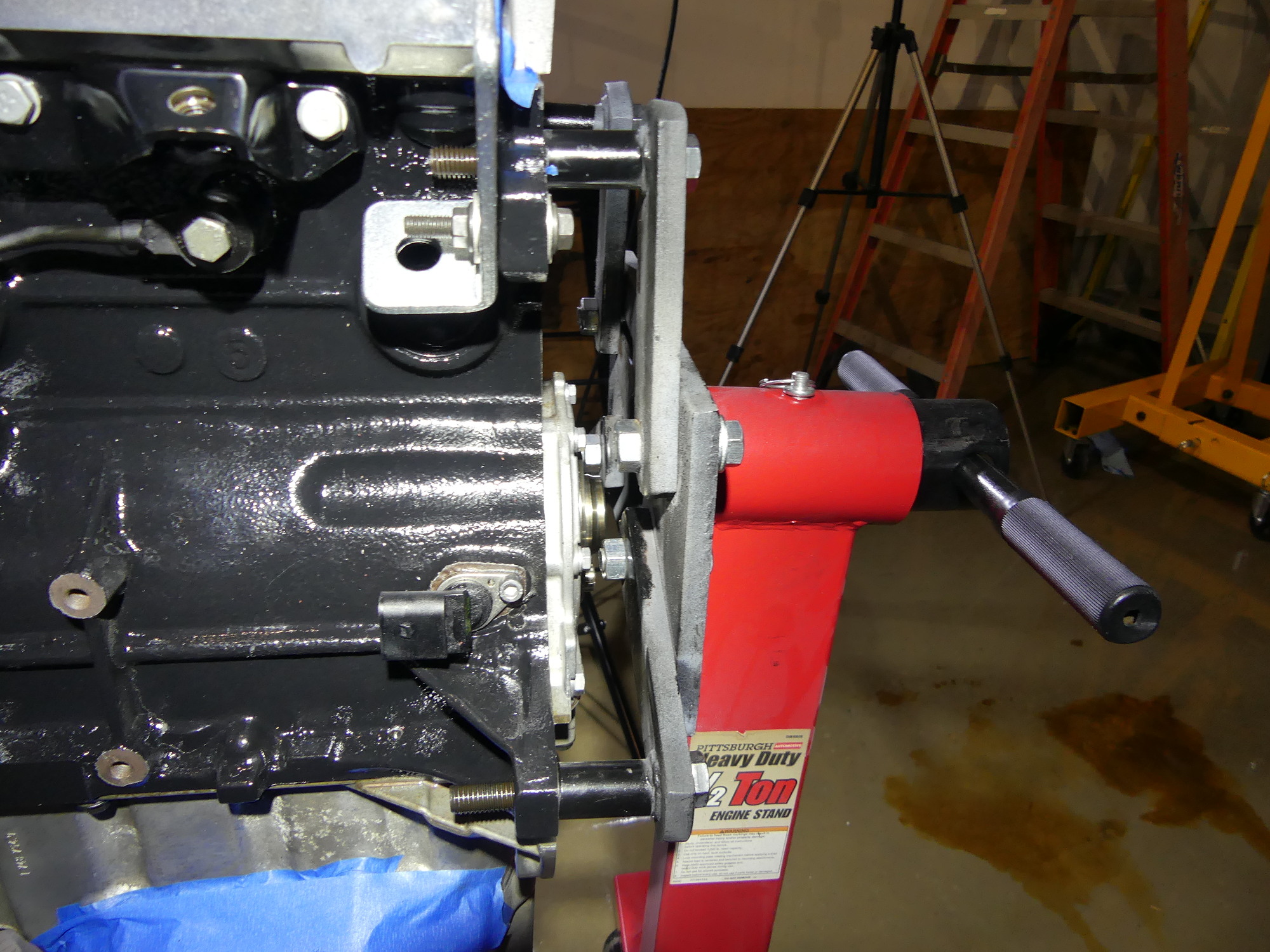 This is the reason I could not install the flywheel on the stand -- the standoffs on the HF stand are not long enough. If I were to work on BMW engines regularly I'd build a stand with longer standoffs. |
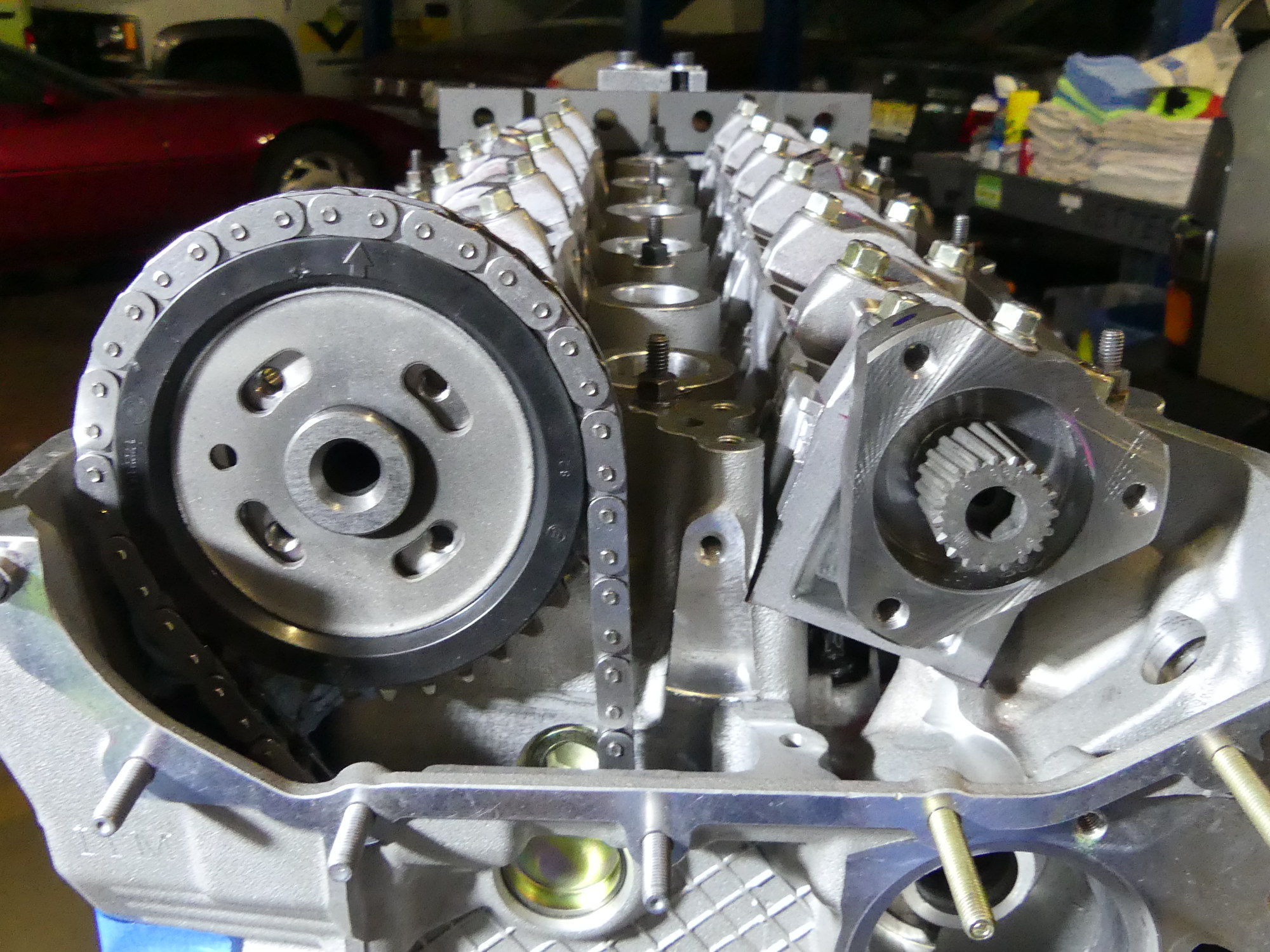 This shows the initial state of the primary timing chain sprocket in relation to the threaded holes in the exhaust cam flange. Note how the holes are biased toward the left side of the slots. |
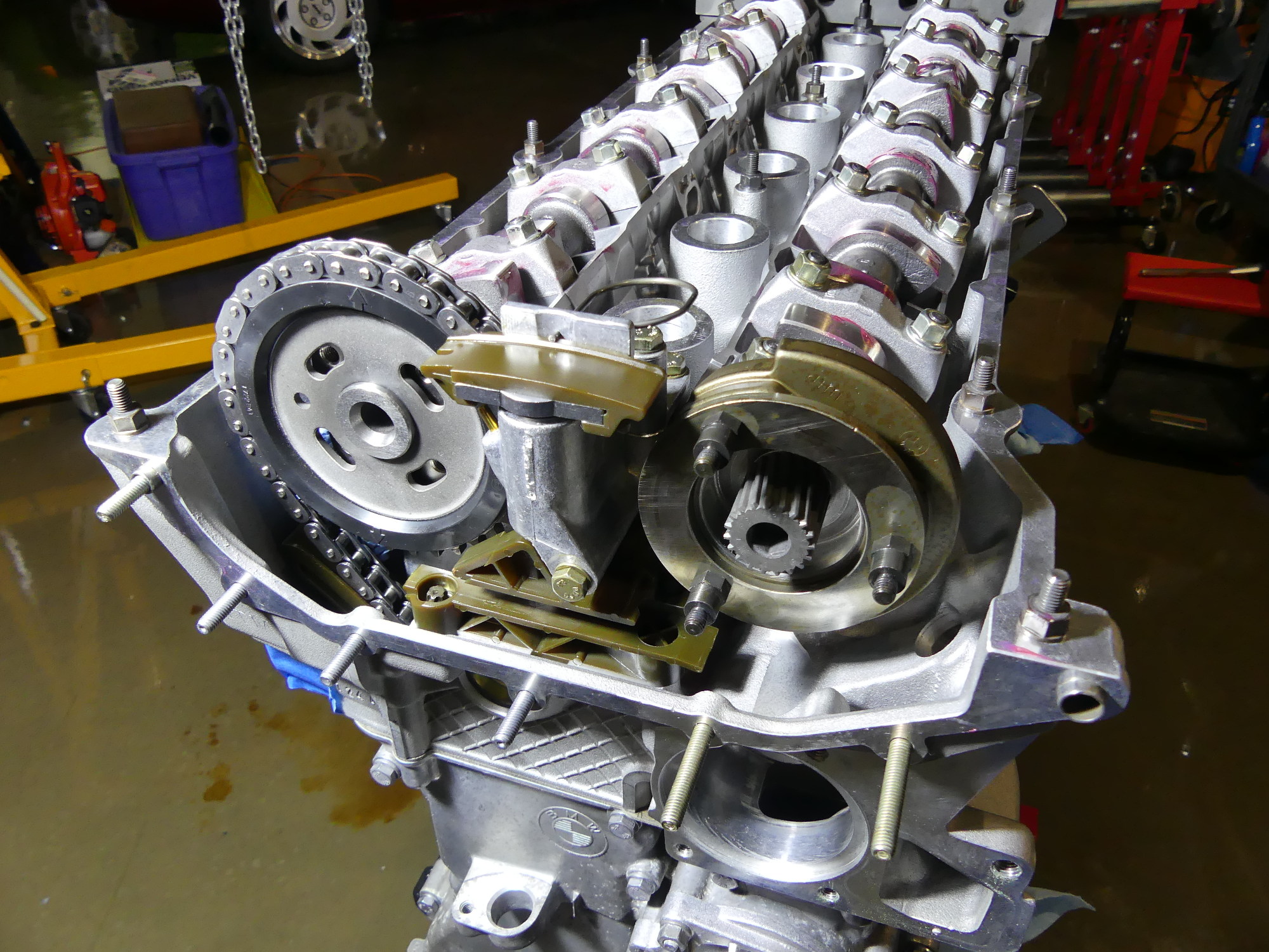 After the primary sprocket is installed it's time to install the lower chain guide and tensioner, both of which are new in this case. The guide bolts are E-torx while the tensioner is standard 10mm hex. |
Turning my attention to the intake cam, I installed the trigger wheel which, fortunately, cannot be installed incorrectly, the 2mm thrust plate and studs. I placed a very small amount of blue loctite on the studs and torqued them down. I then pulled the new secondary timing chain out of its bag and inspected both intake and exhaust secondary timing sprockets. The intake side is designed to rotate over the thrust plate just installed, so I made sure it was well oiled before I test fit it and rotated it back and forth within the limits allowed by the studs. I then inserted both sprockets into the chain, initially adjusting them such that the arrow on the exhaust sprocket was pointing mostly up. After putting a bit of oil over the helical shaft I mated the assembly with the engine.
At this point I stopped and checked to ensure that the slots on the exhaust sprocket were centered over the threaded holes in the exhaust cam flange and the slots on the intake sprocket were centered over the standoffs, again, per TIS requirement. I got lucky and found the alignment was perfect out of the gate. Had either sprocket been out of position it would have been a simple matter to remove the assembly and rotate the sprocket(s) accordingly. Wrapping up the intake side was a matter of installing, in order, the 2mm thrust plate, plate spring, and 4mm thrust plate. Then I put a bit of blue Loctite on the studs and torqued the nuts to retain this sandwich of parts. This compressed the plate spring and left at most a couple threads exposed on each stud.
To prepare for the timing procedure I cleaned the external torx bolts used to secure the exhaust sprockets to the cam and then applied some blue Loctite before fastening them hand tight. I took my time doing this and made sure that I held each bolt tightly and deliberately, since despite cramming some towels down in front of the sprocket, I wanted to minimize the risk of dropping a bolt into the timing cover.
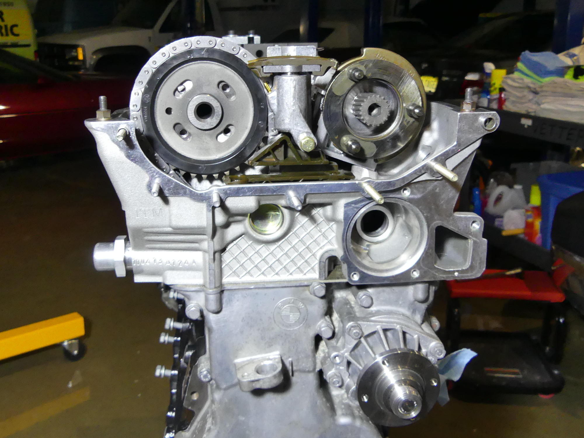 This shows the makeshift timing tool installed in place of the primary chain tensioner. As the tool is installed in the head the primary sprocket rotates counterclockwise and the threaded holes move toward the center of the slots. |
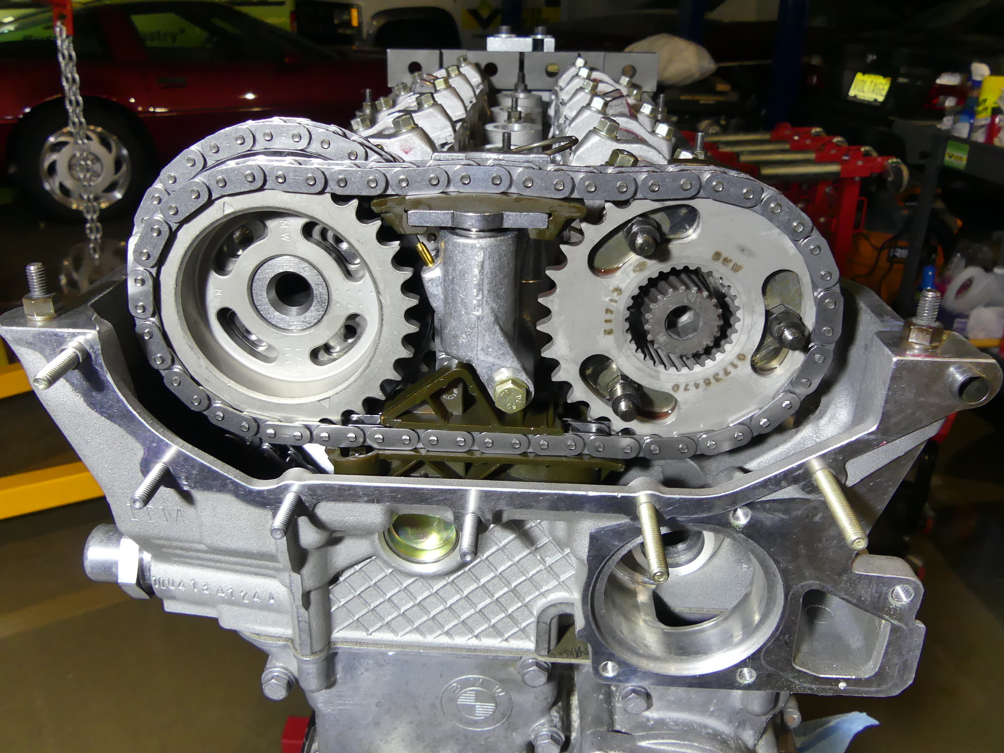 After oiling the teeth and rear of intake side secondary timing chain sprocket I put both sprockets in the chain and installed them such that the threaded holes and studs were in the center of the corresponding slots. |
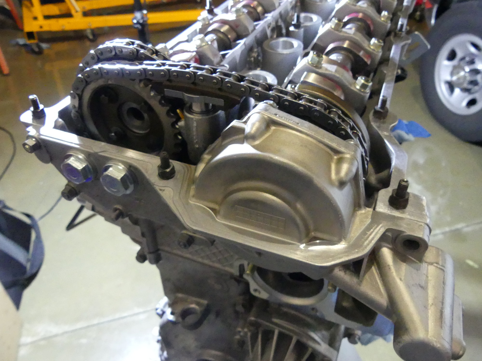 The VANOS installed, sans VANOS solenoid and a few mounting nuts. Those will go in tomorrow as I wrap up the build and prepare to transport the engine, transmission and chassis back to my technician this week. |
Timing the M52 is actually a pretty simple process but it does require a special tool and a torque wrench capable of applying a 1Nm (0.7 ft*lbs) torque. Lacking those tools, a makeshift tool can be constructed using the primary timing chain tensioner itself. The tensioner consists of a piston that inserts into a body along with a spring. I pulled the piston out to remove the internal spring and then dropped 8 US pennies into the body before reinstalling the piston. This creates an incompressible tool that is used to apply a constant force to the primary timing chain guide as required to take up slack in the chain.
Screwing the tool into the head causes the primary timing chain sprocket to rotate counterclockwise, such that the threaded holes in the exhaust cam flange to appear to rotate clockwise within the slots on the sprocket. The farther the tool is screwed into the head, the more force it applies to the chain guide and the more the sprocket rotates. The goal is to screw the tool into the head with a minimum of torque (I used two "weak" fingers) until it firms up, and then turn the tool an additional 20 degrees or so to approximate the 1Nm that would be applied to the factory special tool. Regardless of the tool used, it must remain installed until the sprocket bolts are properly torqued at the end of the procedure.
The technique required of the makeshift tool is made somewhat more challenging by the fact the tool tends to tighten up progressively, as opposed to suddenly, so it takes some experience and finesse to know when to stop and apply the 20 degree additional torque. I probably installed it three or four times before I felt comfortable with the result.
At this point I cleaned and applied blue Loctite to the four e-torx exhaust sprocket mounting bolts and inserted them through the mounting plate and into the threaded holes in the exhaust cam flange. I only hand tightened these bolts for now, as the secondary timing chain sprockets must be allowed to rotate during the VANOS installation procedure, but the bolts must be present to proceed as they ultimately act as stops to prevent the sprockets from rotating too much one way or the other.
Installing the VANOS
Installing the VANOS is a little tricky and, if not done correctly, will cause VANOS fault codes. Naturally, I did a lot of research on this topic and found a great video that adequately demonstrated the correct procedure but I still wound up R&Ring the VANOS unit a half dozen times before I saw exactly what was depicted in the video -- specifically, the VANOS housing pulling in the moment the sprocket begins to rotate counterclockwise.
On the second to final installation attempt I got what I expected, but I couldn't remember if I had rotated the sprocket fully clockwise prior to pulling it counterclockwise, so removed the unit one more time and tried again. This time I found the helical gear positioned with very little of the teeth showing (perhaps 2mm) beyond the thrust plate, and then watched as the housing practically lept toward the engine as I began to move the sprockets with the wrench. I considered that perfect and stopped there. If I get a VANOS fault it won't be due to negligence or laziness on my part.
With the VANOS installed I tightened the external torx bolts on the exhaust cam to 16 foot pounds in a cross-pattern before pulling the makeshift timing tool, replacing the pennies with the spring and torquing the tensioner to 30 ft*lbs. I then wrapped up work for the day by securing the VANOS with the 10mm nuts and installing a new thermostat housing as required to install the engine lifting bracket.
Next Up
I'll slowly rotate the crank a couple times to ensure no undue resistance is felt. Assuming that test passes I'll wrap up the build by installing the remainder of the parts including the VANOS solenoid, intake cam position sensor, oil filter housing, and exhaust side engine mount. That should clear the way to put the chassis back up on the lift to tackle a few last minute items in prep for delivery to my technician next week.