


Thursday, September 7, 2017
Response From Beisan About Radial Play
I sent email to Beisan to seek advice for the apparent lack of radial play of my VANOS following installation of the anti-rattle kit. Within a day I received the following response:
This is normal and is no issue. It's due to the snug axial fit. When the engine is running and the bearing is rotating the radial play will be accessible. The bearing parts don't experience wear. The play you found was there when the vanos was new.
So I think it's safe to say that the VANOS kits were installed properly, no adjustment is needed, and the radial play will appear once the bearings are bathed in oil again.
Engine Machine Work Update
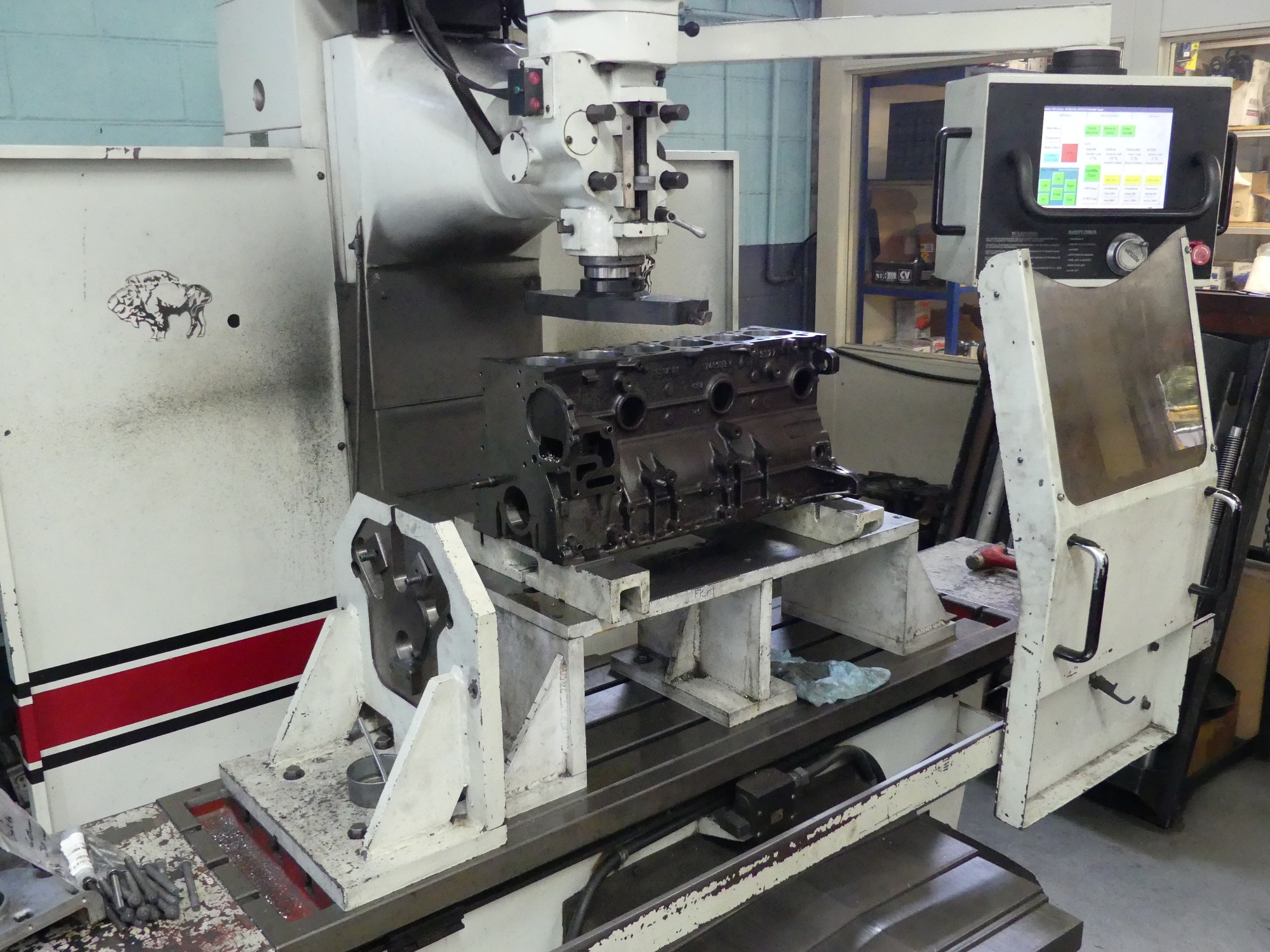
Several weeks ago while prepping the block for delivery to the machinist I attempted to remove the primary timing chain rail support pin. The ETK described the part as a "bolt", implying that it was threaded into the block like the other supports. I should have known better, as the other supports had hex flats milled into them for removal while the pin did not. Regardless, I attempted to remove the pin with a pair of pliers. Despite protecting the jaws of the pliers and the pin itself I wound up marring the surface of the pin before giving up on the task. When the new part arrived I learned why my efforts were futile -- the new part had no threads and was in fact designed to be pressed into the block. So this meant my machinist would have to pull the old pin and press in the new one. And that led me to deliver the pin to him today before he wraps up the job and returns everything to me sometime in the next few days.
When I arrived I found my block on the mill and my crankshaft on the balancing machine. I initially looked the block over and realized that while the machine work looked good, the exterior of the block was not cleaned properly. Although it's obvious the block was cleaned in some way the appearance is not consistent with a block that has been properly baked and/or shot blasted. The sides of my block still have patches of paint attached and are rusty overall despite being drenched in preservative oil. The annoying thing about this is that I could not have been more clear about my requirements both verbally and in writing, but yet again I have found myself working with a vendor who has utterly failed to keep me in the loop and communicate effectively despite a number of convenient options available. Had the machinist taken the ten seconds required to text me a picture of the block after it came back from the cleaner I would have given it the thumbs down and told him to send it back, but now that the machine work has been completed there's nothing I can do without risking contamination of the block. I will have to wash the block with solvent a couple times to remove the preservative oil, apply primer and paint, and pray that I don't have any issues with paint adhesion.
 As I walked in I saw my block still on the milling machine. At this point the block was finished aside from installing the freeze plugs and oil gallery plugs. |
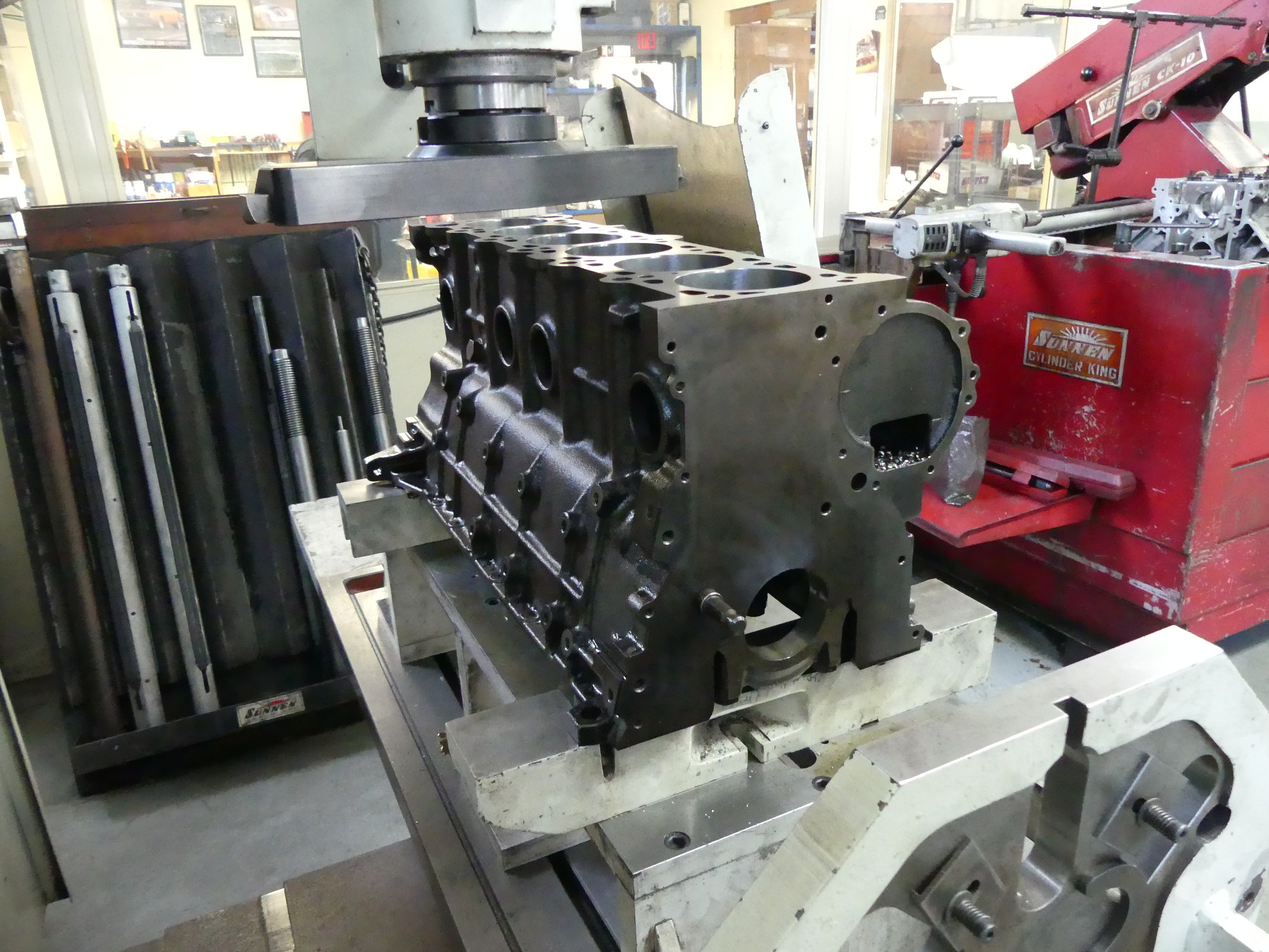 The wet sheen of the block is the preservative oil (WD40) I requested be placed on the block to prevent flash rust, but I'm not sure it was applied soon enough as the sides of the block are still rusty. |
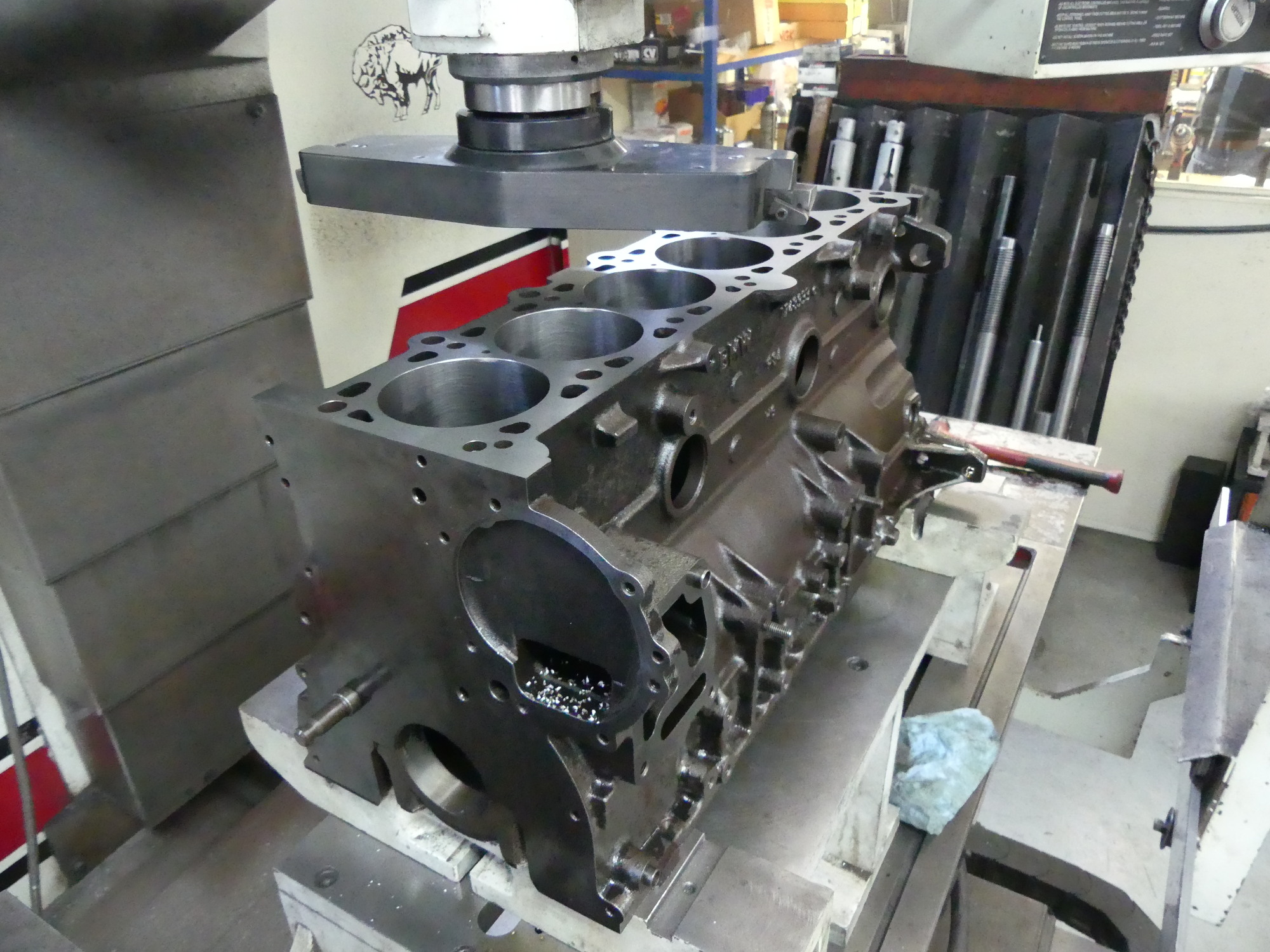 The deck cleaned up with a mere 4 thousandths removed. If you look very carefully you can also see a subtle but important chamfer at the top of the cylinder. There is also a similar chamfer at the bottom of the cylinder. |
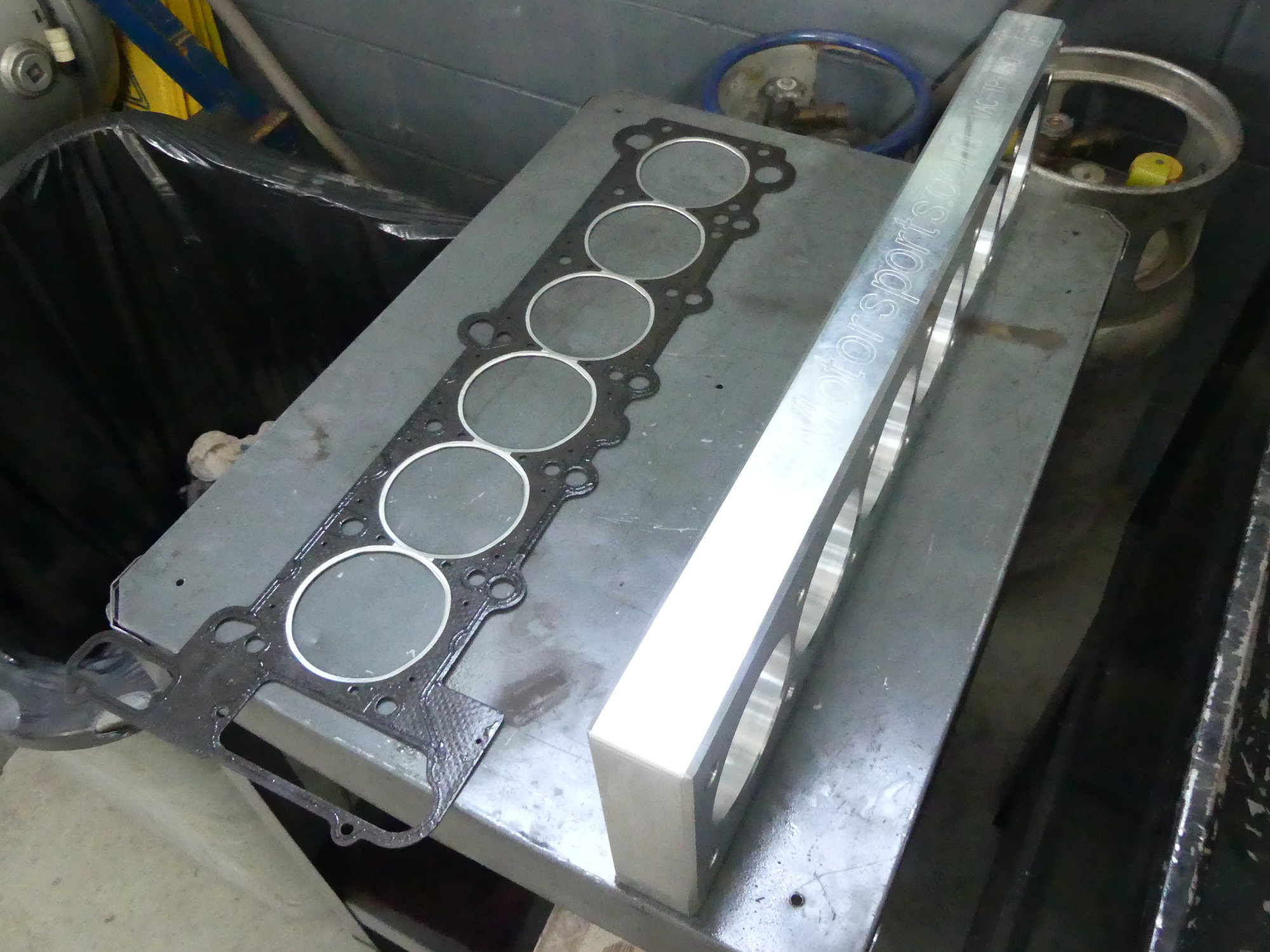 I goofed and forgot to provide a head gasket as required to install the torque plate. My machinist acquired one from my local BMW indy, Mr. M Car. Since I'll likely pay for this I'm keeping it as a trophy. The final build will use a new BMW gasket. |
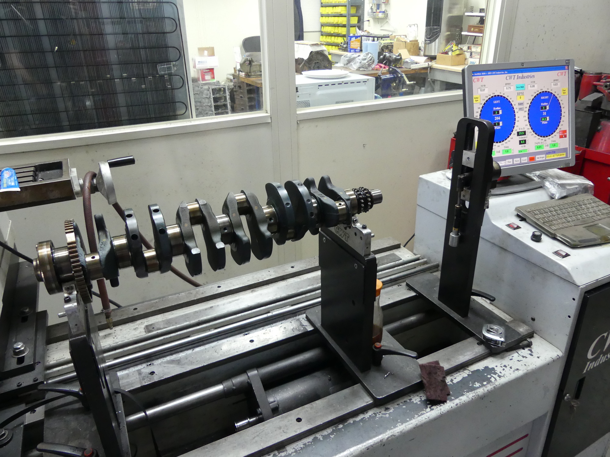 My crank on the balancing machine. While not shown here, the balancing took place with the flywheel and damper installed on the crank in order to balance everything as a system. I'm expecting the engine to run as smoothly as it did when new. |
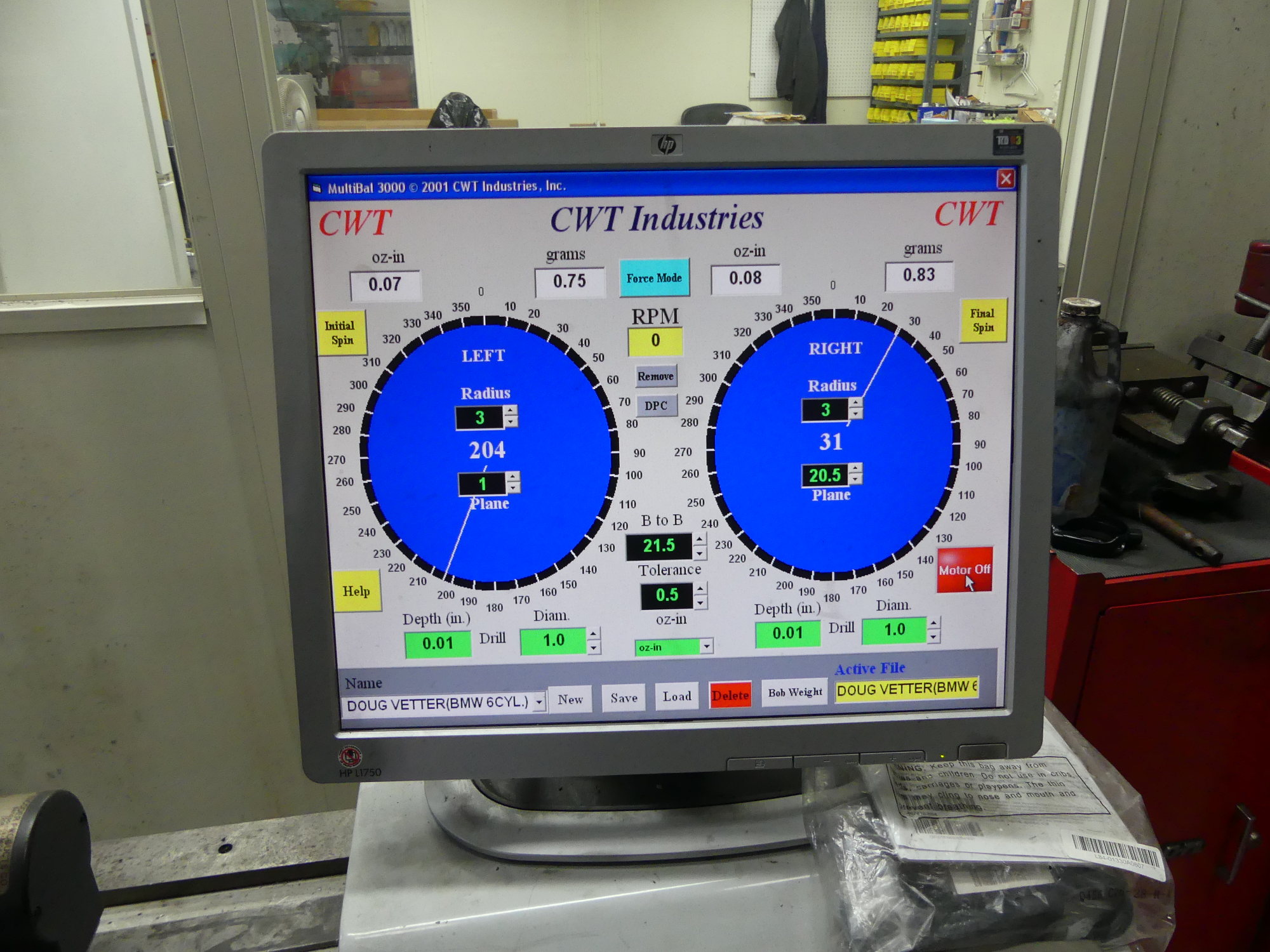 I won't pretend to understand everything about this display but I can say that it shows my crank balanced to within 0.83 and 0.75 grams on the front and rear respectively. |
I asked him how much material he took off the deck and he said 4 thousandths. From what I've read BMW recommends use of the 13 thou thicker head gasket if more than 8 thou total is removed between block and head. As I will be installing a new head and my total is therefore only 4 thousandths I'm fairly confident I can use the standard thickness gasket. I'll confirm this with my technician. Speaking of the gasket, I was not aware that my machinist required a gasket to be installed between the block and the torque plate so I never provided one, but he obtained one on his own from the local BMW independent (Mr. M Car). When I asked why this was required he said that the reinforcements built into the head gasket can induce additional pressures on the block and while the effects are subtle and difficult to measure (at least within the resolution of his instruments) the job is correctly done with a gasket installed.
He also showed me the timing cover that was installed during the milling process and how, even with four thousandths removed from the deck, only a portion of the timing cover met with the cutters. He was quick to point out that this was not due to an installation error on his part, as the timing cover uses locating dowels to ensure it is always installed in the same position on the block. As a result, it's pretty clear this is a result of a machining error committed during the original manufacturing of the timing cover. My guess is either the top surface was milled without the cover being perfectly vertical in the machining fixture or the locating dowels and perhaps the remaining holes as well were drilled slightly askew. In any case, this is no factor in the build, as the head gasket will more than compensate for this minor difference in height.
As I indicated earlier I requested the machinist balance the crank with the damper, chain sprocket, and flywheel attached. The machinist told me that initially the rear of the crank was about 10 grams out, with much of that likely being related to the flywheel and related components, but he was ultimately able to get the entire system balanced to under a gram (0.8 grams, specifically). Examining the crank journals I noticed how he continued drilling the same holes BMW used to balance the crank during manufacturing, and that he drilled in more than one spot along a given journal, just as BMW did.
At this point he had not polished the crank. I asked him whether he felt it needed polishing and he said he thought he could improve on its current state, but that polishing is typically the last step in the process. He also noted that for a crank in good shape like mine he typically uses a well worn polishing belt that may have started life as a 400 grit but is now somewhat finer. The goal, of course, is to polish the journals to a mirror-like finish rather than remove a lot of material. And for the record, I provided the machinist with BMW's crank dimensions and bearing specifications and emphasized that if he removes material the journals should be consistent with one of those bearing sizes. Since my crank started life as a yellow crank, after polishing I'm expecting to install a full set of green bearings, but I'll have to wait and see what my measurements reveal. I took quite a few pictures and video of the old crank so I'm looking forward to seeing the end result.
More Assembly
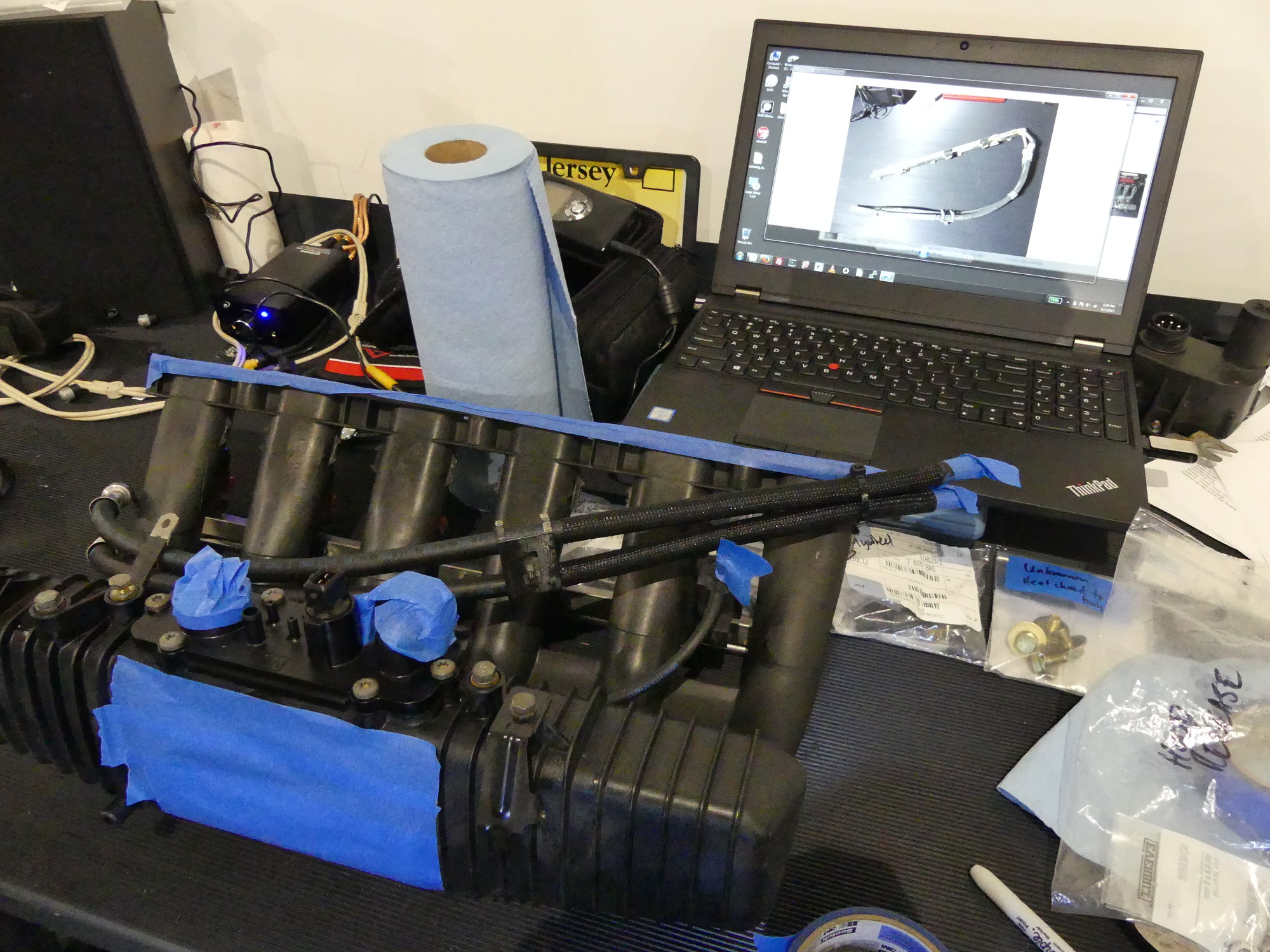
Some additional parts I ordered came in the other day so I was able to assemble the transmission support with new mounts, as well as install a new intake manifold cover and gasket. I also decided to attach the flexible fuel lines with special connectors to the fuel rail so the assembly matches what my technician removed from the car.
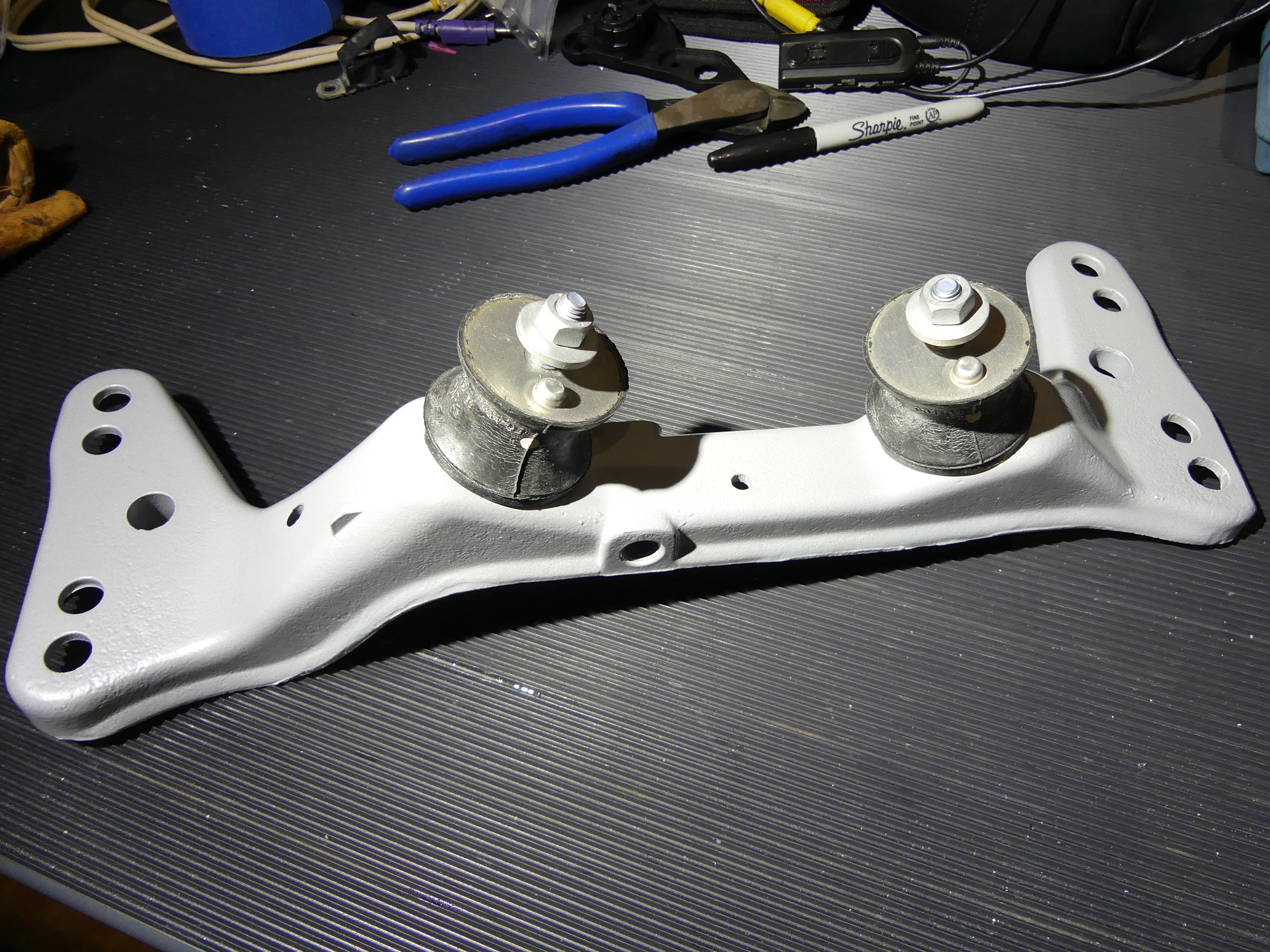 I finally received the new hardware needed to assemble the transmission support. My tech removed the original support with bushings installed like this so my goal here was to provide the reworked assembly in the same condition. |
 The nut and washer on the bottom of the transmission support that fixes each bushing to the support is now Zinc-Nickel plated, which should help them remain corrosion free for as long as possible. |
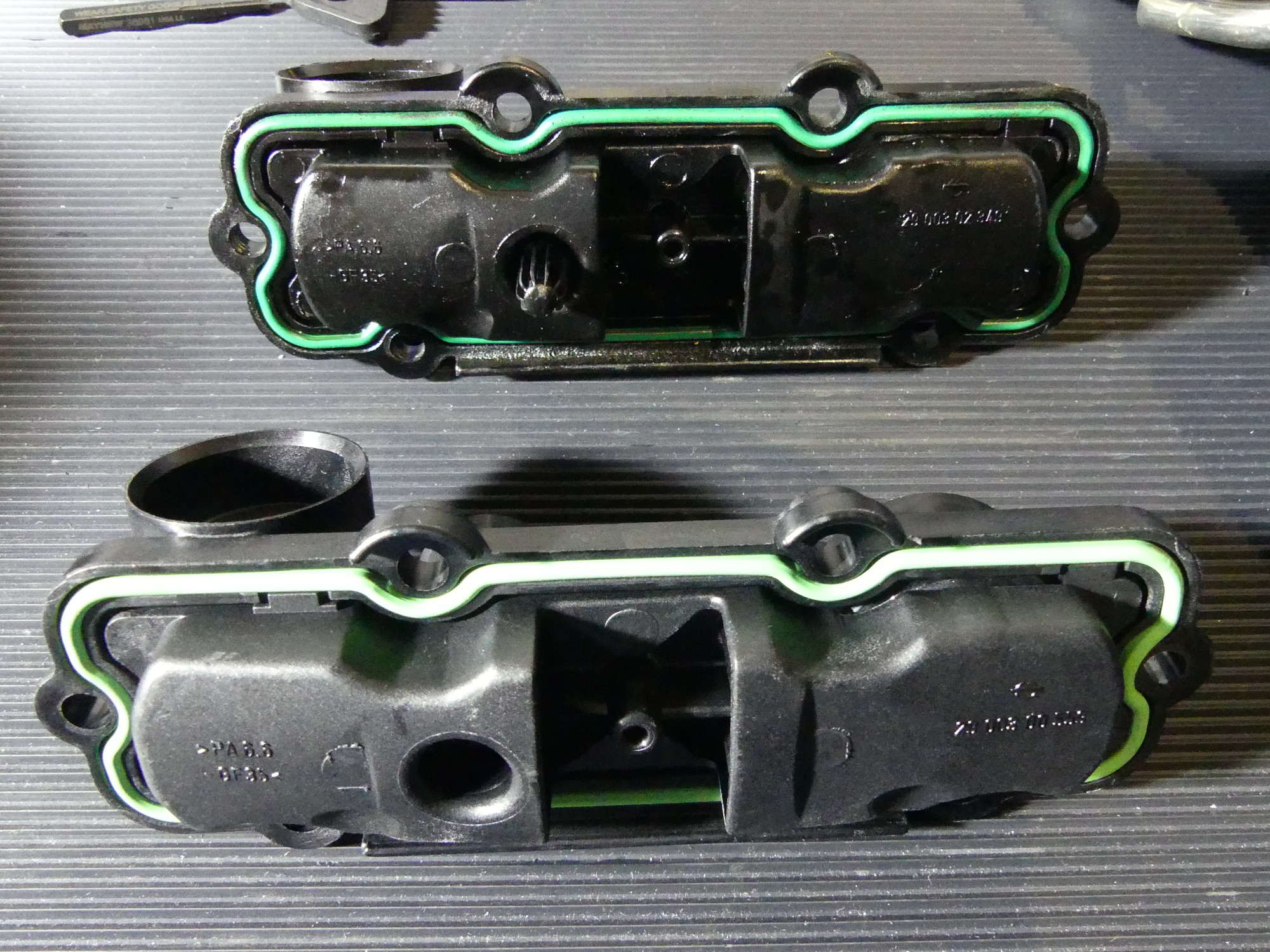 The new intake manifold "cover" and gasket is shown in front while the old one is in the rear. I replaced the cover because I couldn't clean it effectively, while I replaced the gasket for good measure. |
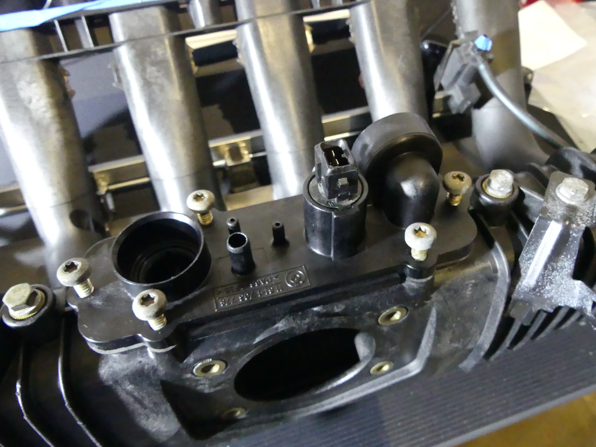 Here I've partially inserted the torx screws used to secure the cover to the intake manifold. I wound up spritzing these with Zep45 lubricant so I could accurately and evenly torque the fasteners to 40 inch-pounds. |
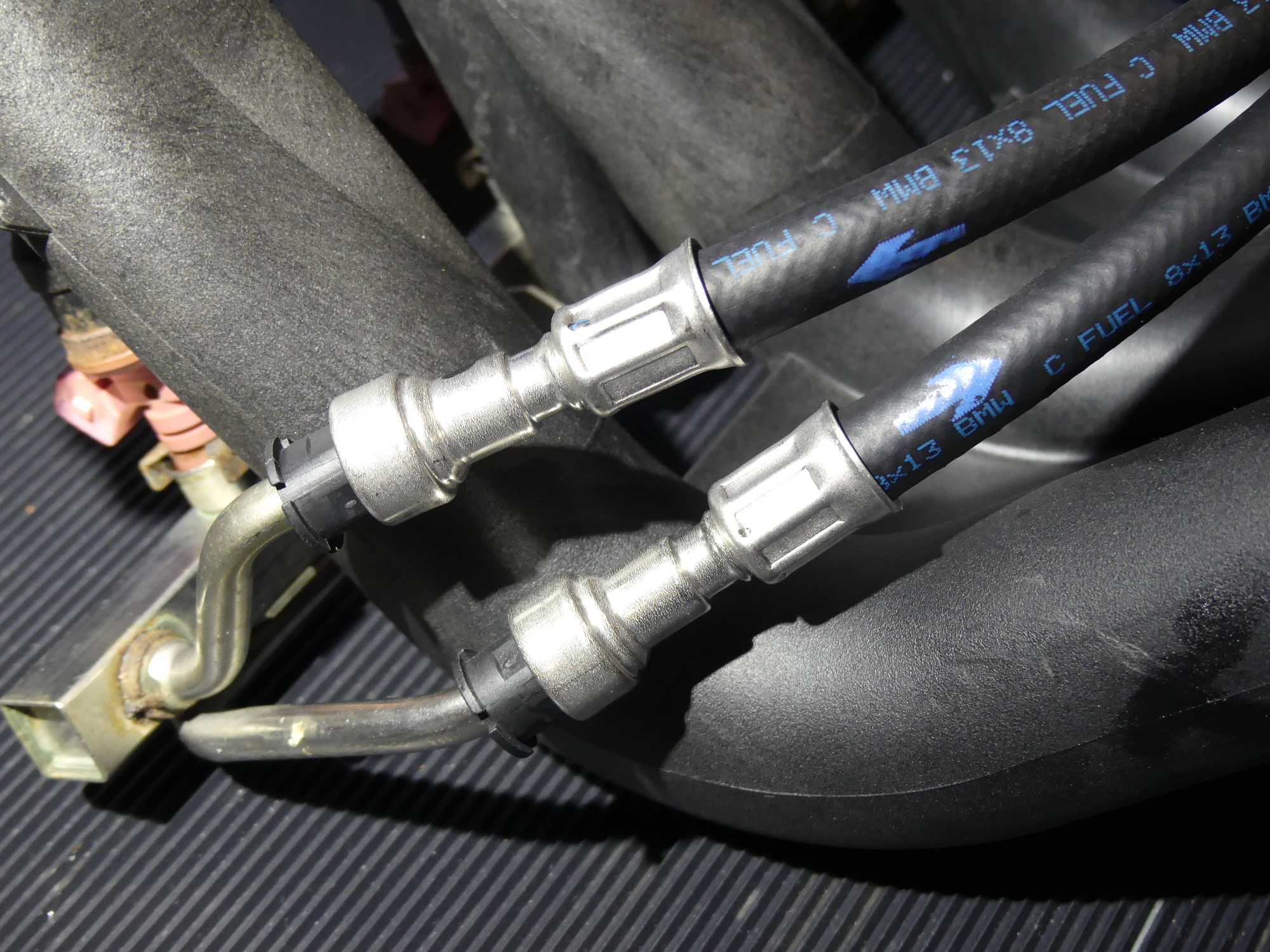 The new fuel rail hoses have been attached to the fuel rail hardlines. The hoses appear physically identical aside from the arrows on the lines that indicate the feed and return sides. They are separate part numbers. |
 This odd two-hose clamp had to come from Germany and as a result took longer than most parts to arrive. The original was fine, but the hinge is made of plastic, so I bought one just in case I broke the other one. |
 I took this picture to provide some perspective on how important it is to take pictures and video, if possible, during disassembly of any major project. No matter how obvious you think something goes together, chances are you'll forget the details. |
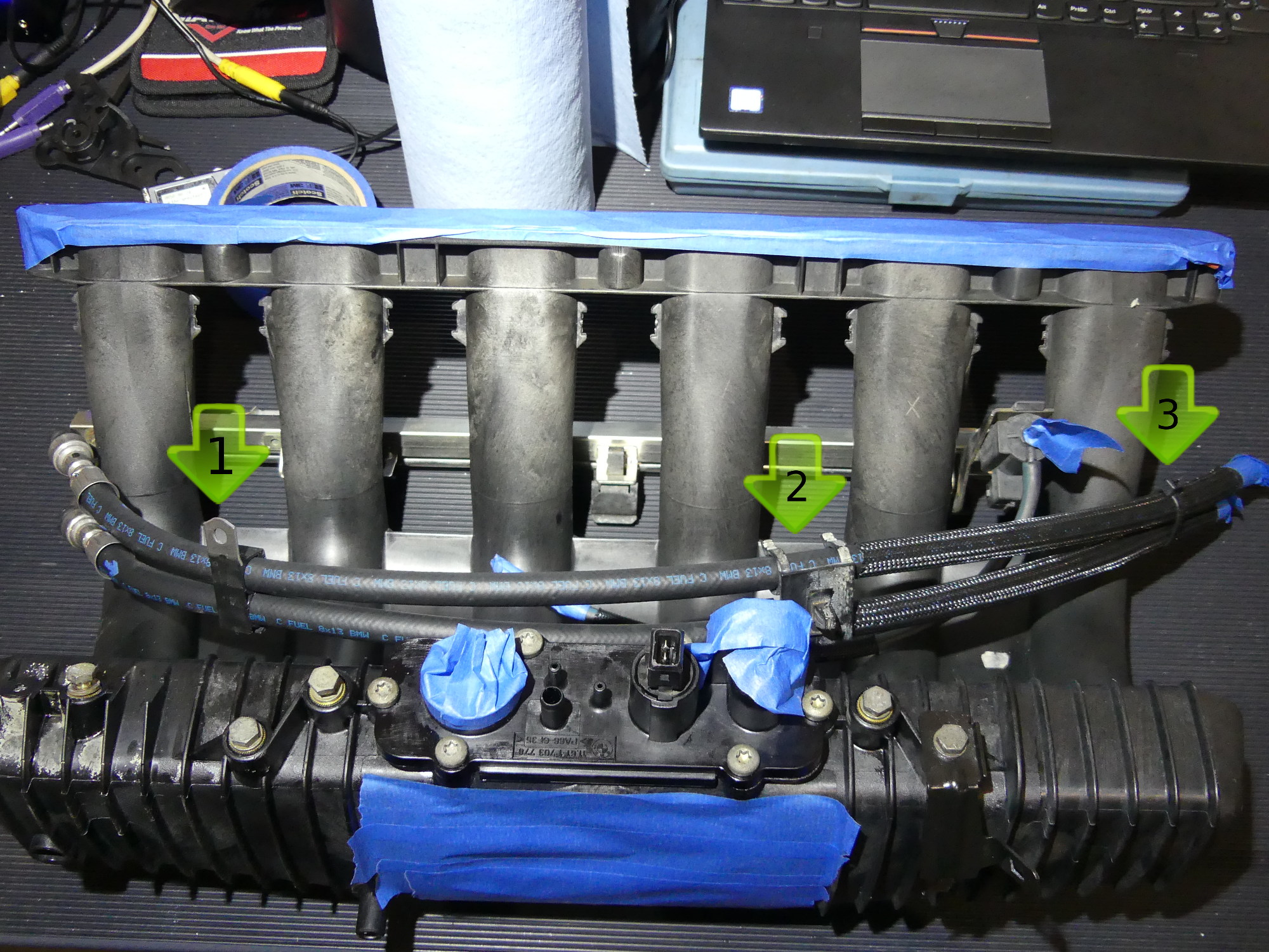 The fuel rail hoses are constrained by a two pipe clamp (1), an odd plastic hanger (2) and a ty-wrap (3). I used the pictures I took during disassmbly to establish the correct orientation and location of these parts. |
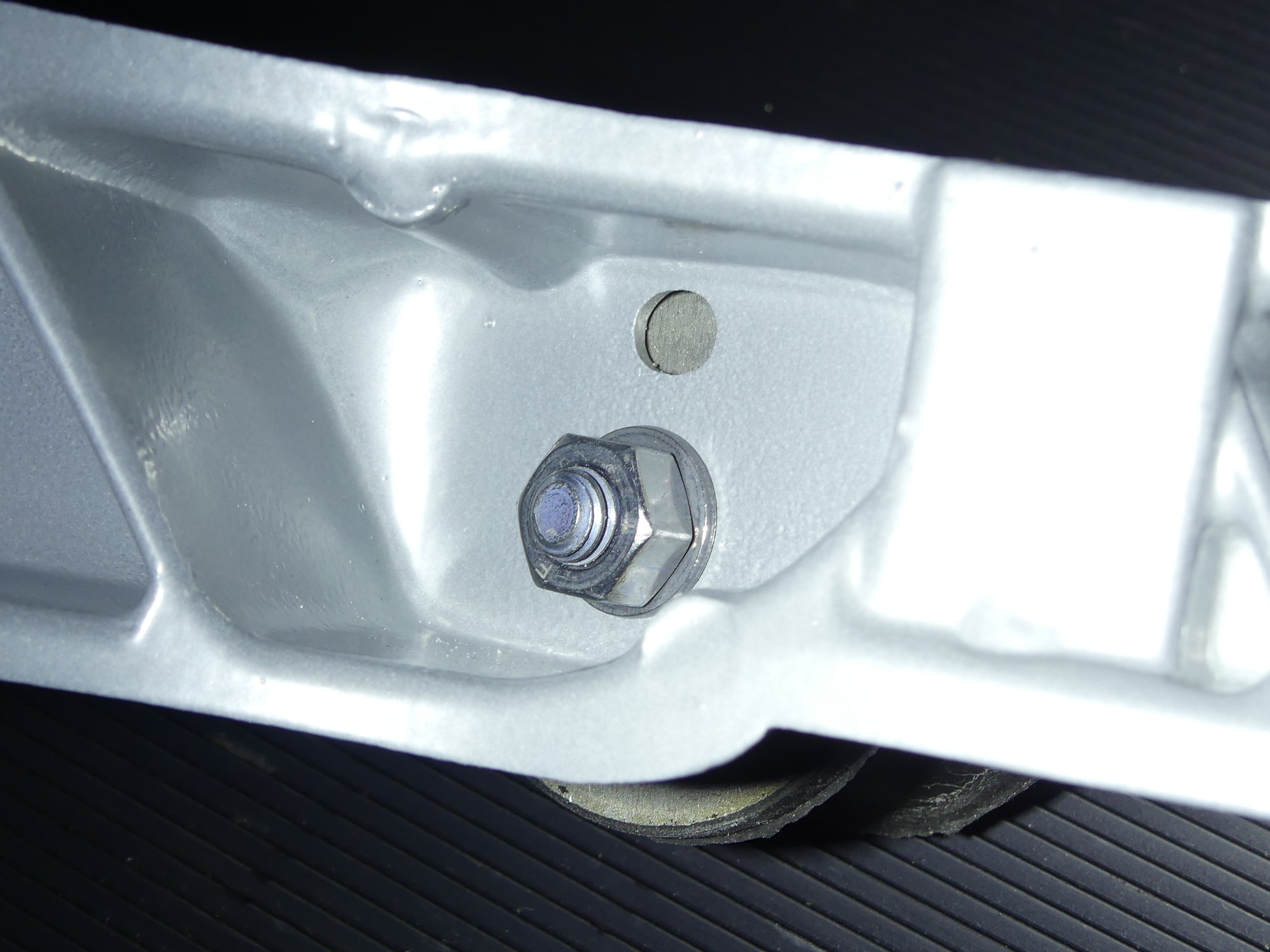
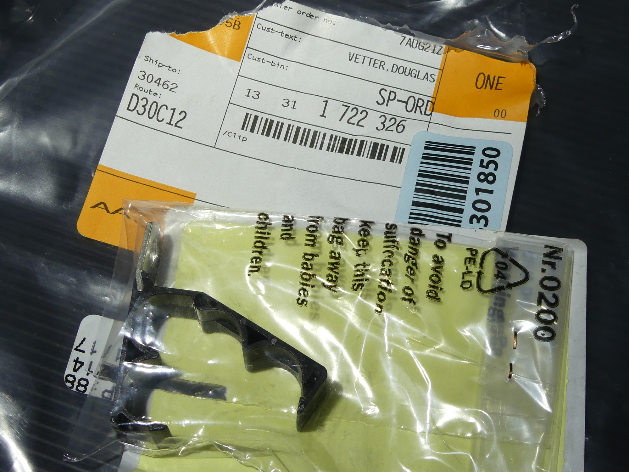
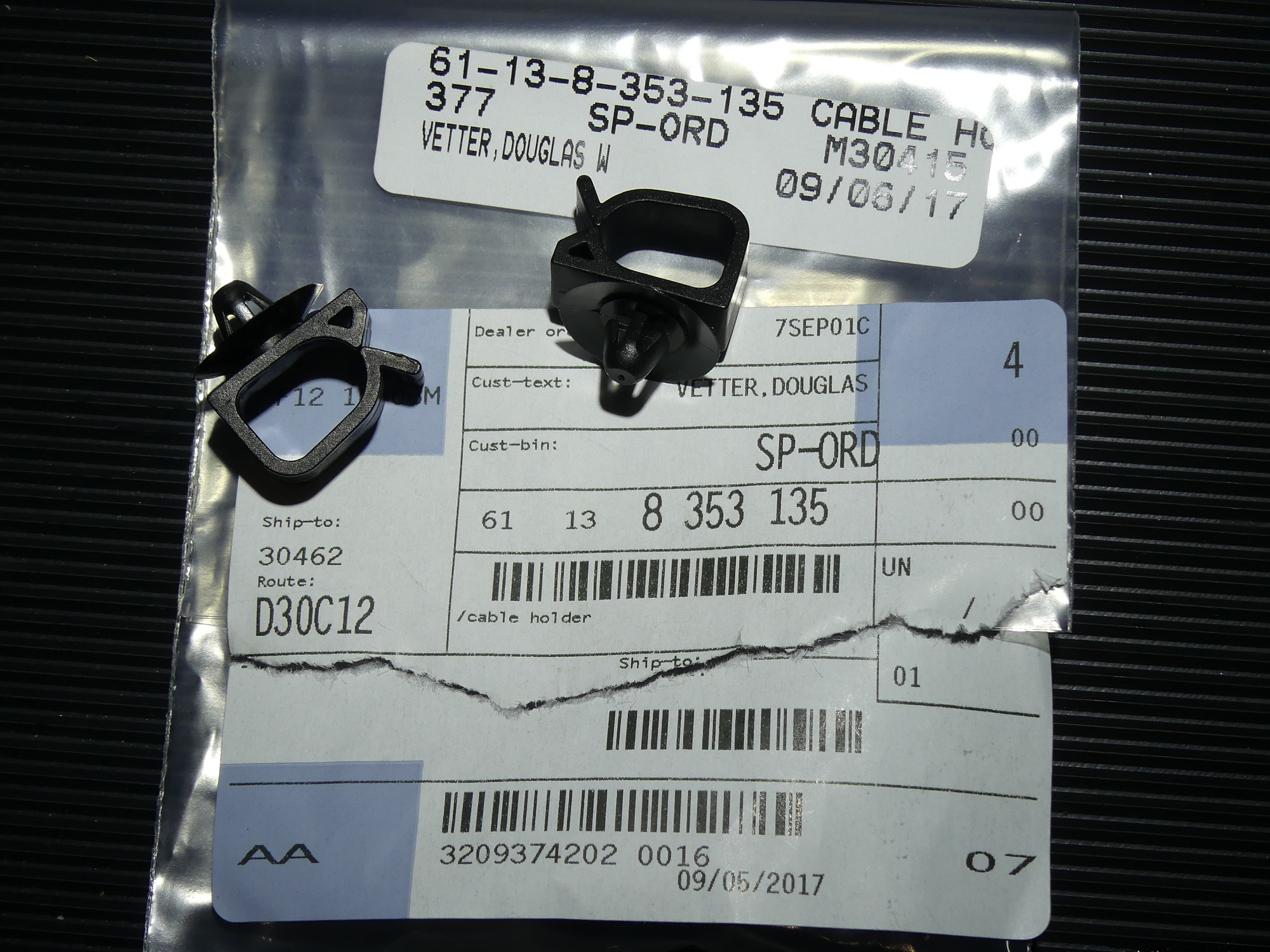 Two of these clips are used to support the wire harness at each corner of the front support. I ordered the wrong version of this clip last time but received and installed the correct ones shown here. |
While assembling the transmission support I confirmed that the lower nut and washer I received was zinc-nickel plated, while the originals were likely cad plated, as they were quite rusty. Based on what I have observed with some of the older zinc-nickel plated hardware on the car, ZnNi is far superior to either cadmium or zinc plating with respect to corrosion resistance, and I hope that BMW moves all of its hardware to ZnNi processes over the next few years.
I decided to replace what BMW simply refers to as the intake manifold "cover" and gasket. I replaced the cover because I could tell it was quite dirty internally from receiving the the output of the CCV but I could not effectively clean it. I replaced the gasket simply because I felt it would be good practice. As it turned out the new gasket is slightly fuller and thicker. As expected, it was also far less compressed than the original 20 year old gasket so that should result in an excellent seal. When installing the cover I took time to clean the bolts with mineral spirits and then install them. The problem was, with dry threads, the screws made really disconcerting noises and jerking motions as they were tightened so I removed and sprayed them with a bit of Zep45 lube before I reinstalled them. They went in smoothly this time around and this made it easy to dial up 40 inch pounds (about 3.3 ft*lbs) on my smallest torque wrench and tighten all of the bolts consistently.
While installing the fuel rail hoses I found it necessary to go back over my disassembly pictures to verify the correct orientation of the hose clips. My memory has served surprisingly well during this project so far, proving I haven't quite lost my mind (yet), but there have been a couple instances like this one where I was glad to have taken such detailed pictures of the disassembly process.
Next Up
I'm officially on vacation from the project until my engine parts are returned from the machinist sometime in the next few days.