


Monday, October 2, 2017
Rod Assemblies Installed
Today I installed all of the rod assemblies into the block. This process took a bit longer than expected, mostly because I was taking my time, but also because I had to combine the final assembly process with a plastigauge check of the rod bearings. It didn't help that I ran into a snag and had to seek advice from Steve at TEP, but more about that later.
Normally installing the rod assembly for a plastigauge check wouldn't require clocking the rings, but since I was combining the check with the final assembly process I clocked the rings to JE's specifications. With the piston oriented in front of me such that the exhaust valve reliefs were on the right, I placed the top ring gap to the right and the second ring gap 180 degrees opposed. The oil ring expander gap was checked to ensure that the ends were butted together and not overlapping, and then it was located in the same position as the top ring (toward the exhaust side). The oil rails were spaced on the left side of the pistons approximately 30 degrees to the left of the pin. I'm not sure it really matters, but they showed the top and bottom rails in specific locations so I followed those instructions as well.
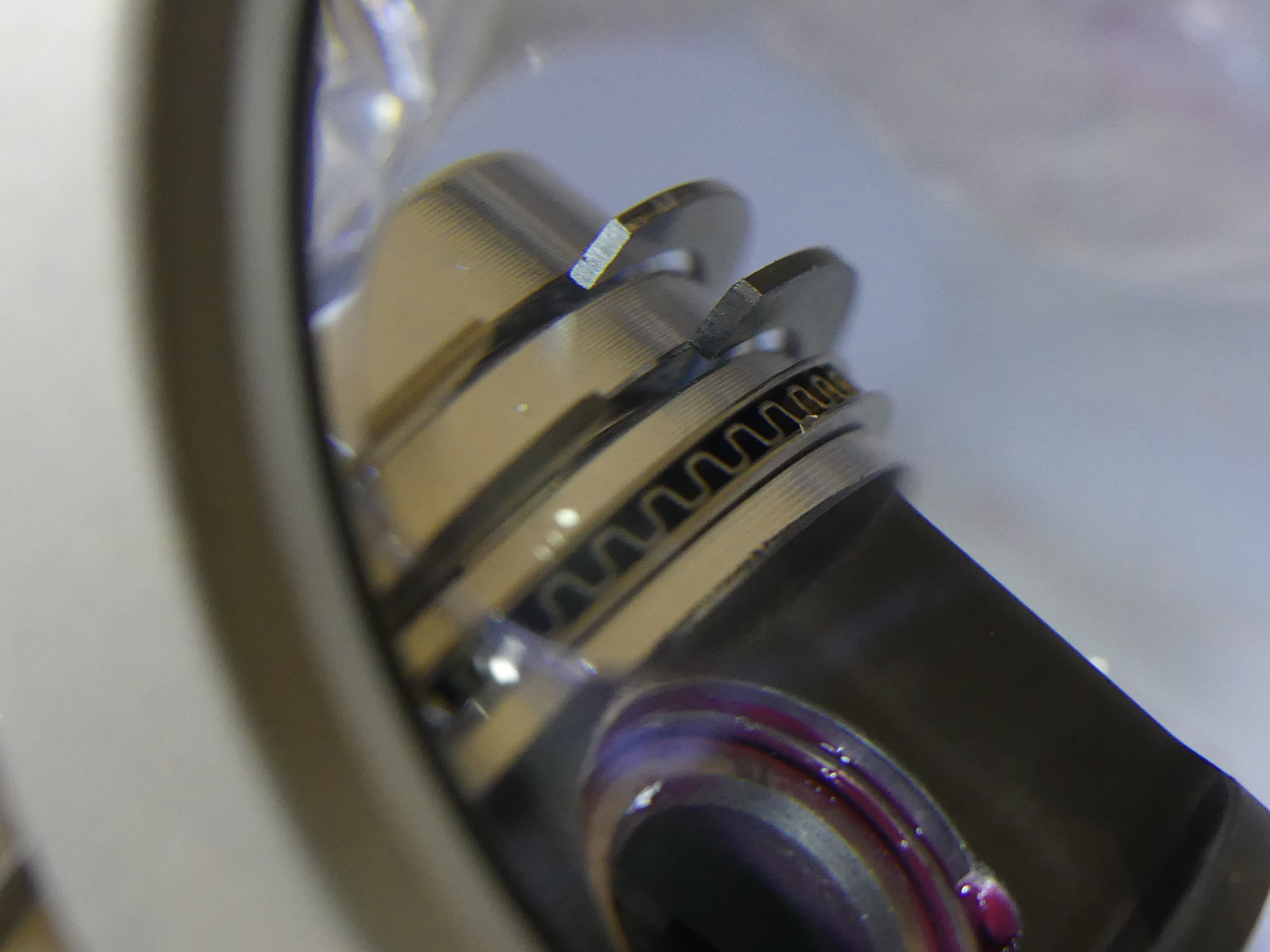 I inspected the filed edge of the rings under magnification before and after deburring and they all looked good like this. The Summit Racing ring filing tool does a nice job. |
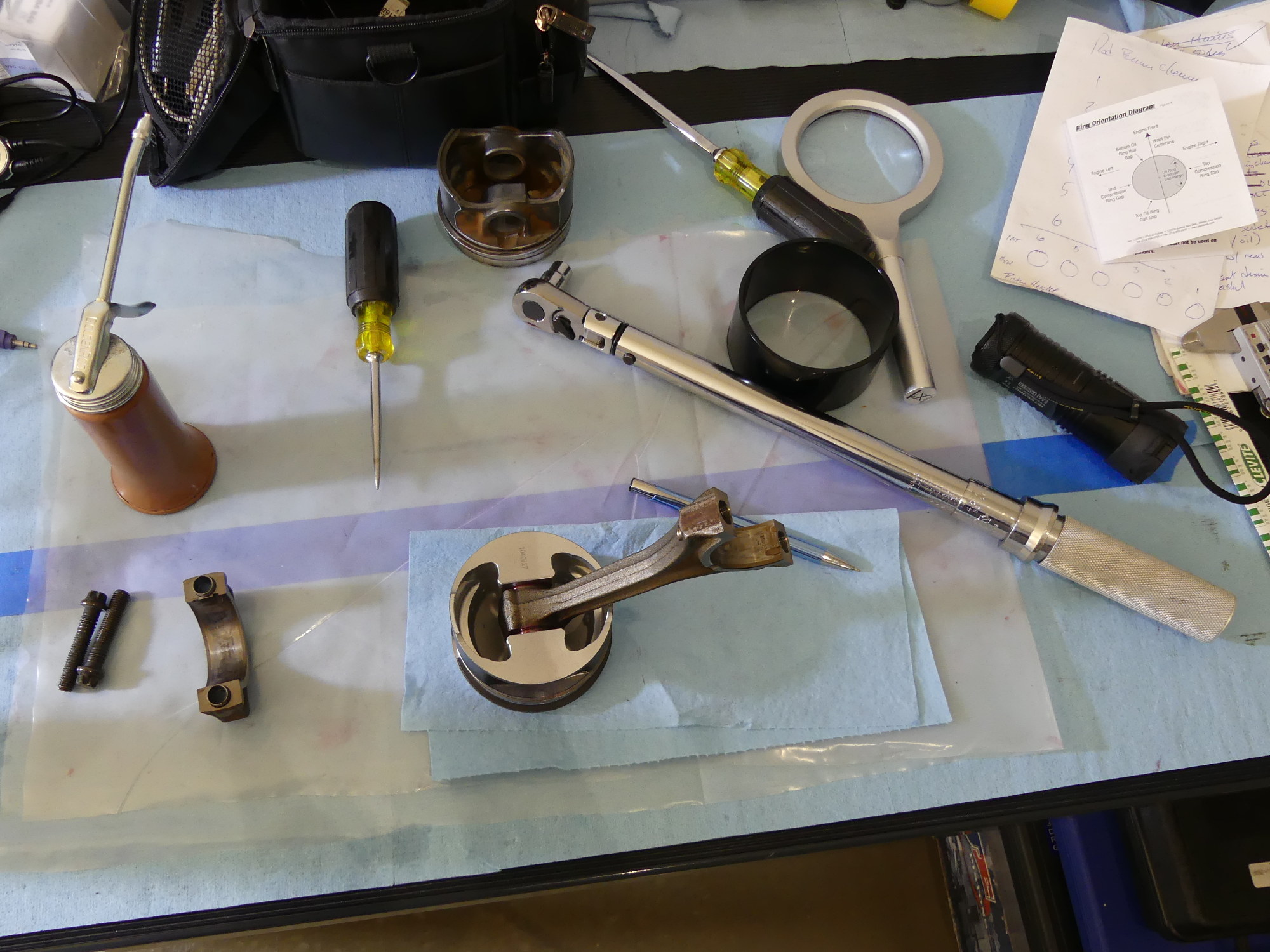 Next I put the rod on the bench to clock the rings. Then I cleaned and installed the bearings in the rod and cap. The black ring to the right of the torque wrench is the tool of the day -- the Wiseco 84.5mm tapered ring compressor. |
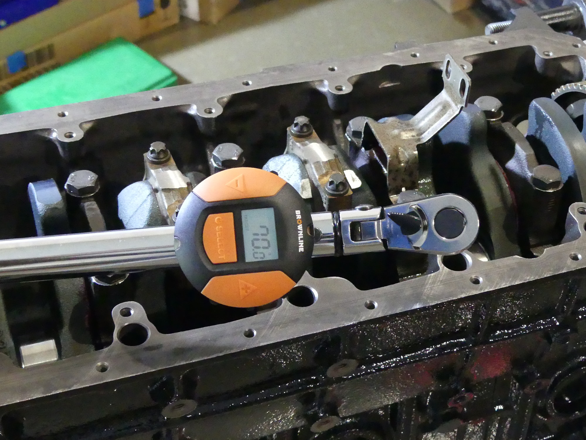 Another tool I used a lot more than I thought I would is the Brownline torque angle gauge. I think this is a great option if you can't justify purchasing new torque wrenches supporting torque angle measurements. |
Once the rings were clocked I installed the blue bearing in the rod and the red bearing in the cap. While the bearings came sealed in a plastic bag from the factory I decided to wipe both shells with a blue towel laced with mineral spirits. This process did occasionally result in the towel appearing slightly dirty, so while the bearings appeared dry and free of any preservative oil, it's pretty clear that cleaning them served a purpose. I wrapped up the cleaning process by blowing them dry with compressed air.
Once I was ready to install the piston I prepped the bore with a light film of the break-in engine oil and then squirted a bit of the same oil over the rings before loading the assembly into the Wiseco 84.5mm tapered ring compressor. I'll cut to the chase and say that tapered ring compressors are awesome and no engine builder should be without one. This Wiseco model turned a potentially annoying and tricky operation into a care-free one. I exposed about 1 cm of the piston skirt below the bottom edge of the compressor to serve as a centering mechanism, carefully inserted the assembly into the bore, and while using most of my fingers to hold the compressor firmly to the deck I used my two thumbs, facing each other, to smoothly press the piston into the bore. Each piston went in the same way -- with only one area of hesitation (presumably the oil rails, but I can't be sure). With the piston in the bore I set the ring compressor aside and pushed the piston face about 1 cm below the deck before rotating the engine on the stand to gain access to the bottom of the rod.
In prep for the plastiguage check I carefully brought the rod and its clean and dry bearing smoothly and carefully into contact with the journal. This is one of those tasks that most engine builders never talk about because it's so straightforward (or so it seems), but that's the difference between the Internet and reality. The first time I tried to pull the rod up to meet the journal I could see that it was twisted slightly as compared to the journal. This was visually obvious so I stopped before the rod ever met the journal and corrected the problem by rotating the rod in the bore along with its piston. But even after I did that, I noticed on a couple of the assemblies that the rod seemed to get stuck as it started to mate with the journal. This occurred because the little end of the rod rod was not centered on the pin and this caused the rod itself to be off center. I tried to fix this by sliding the rod to the center of the pin by hand but I couldn't get enough leverage. Complicating matters was the tight fit of the bushing to pin, which served as a brake of sorts, preventing the rod from sliding easily on the pin. This was easily remedied using a long flat blade screwdriver which I used to give the little end of the rod a bit of a nudge. That freed the rod and allowed it to center on the pin. With the rod perfectly straight the big end smoothly mated with the journal.
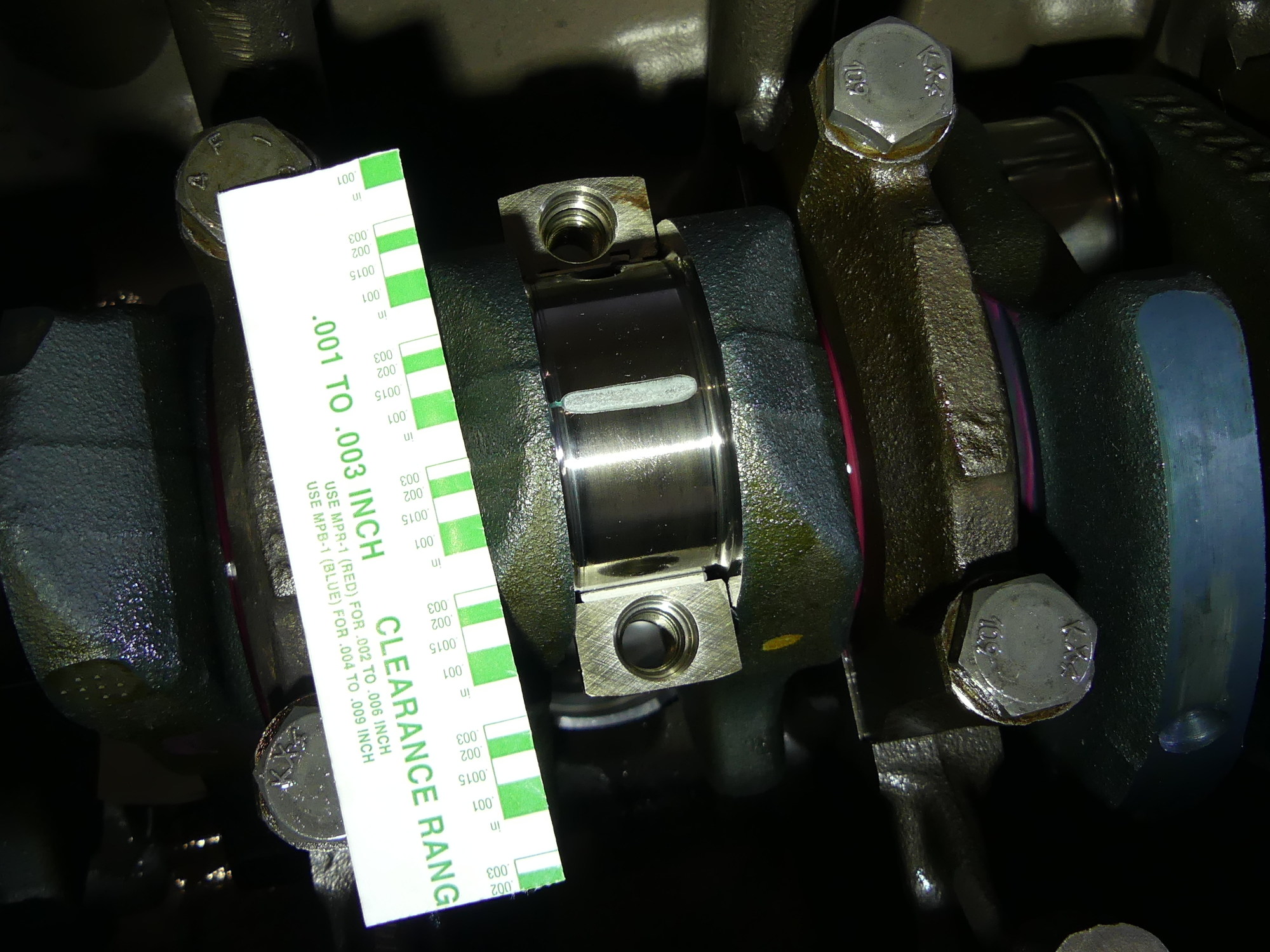 The first of six rod bearing checks. This shows a 1.5 thousanth clearance with a just a hint of taper on the left side. The gauge is compressed less there, which means the journal is smaller and the clearance slightly larger. |
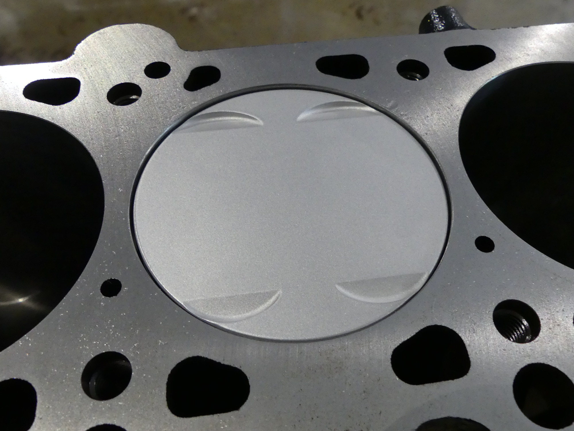 I had to stop and call Steve at TEP when I saw this. I expected the depth between the deck of the block and the face of the piston to be roughly 1.7 after milling, but it turned out to be closer to 1.1mm. Steve said 1.1 to 1.2mm is correct so I'm good to go. |
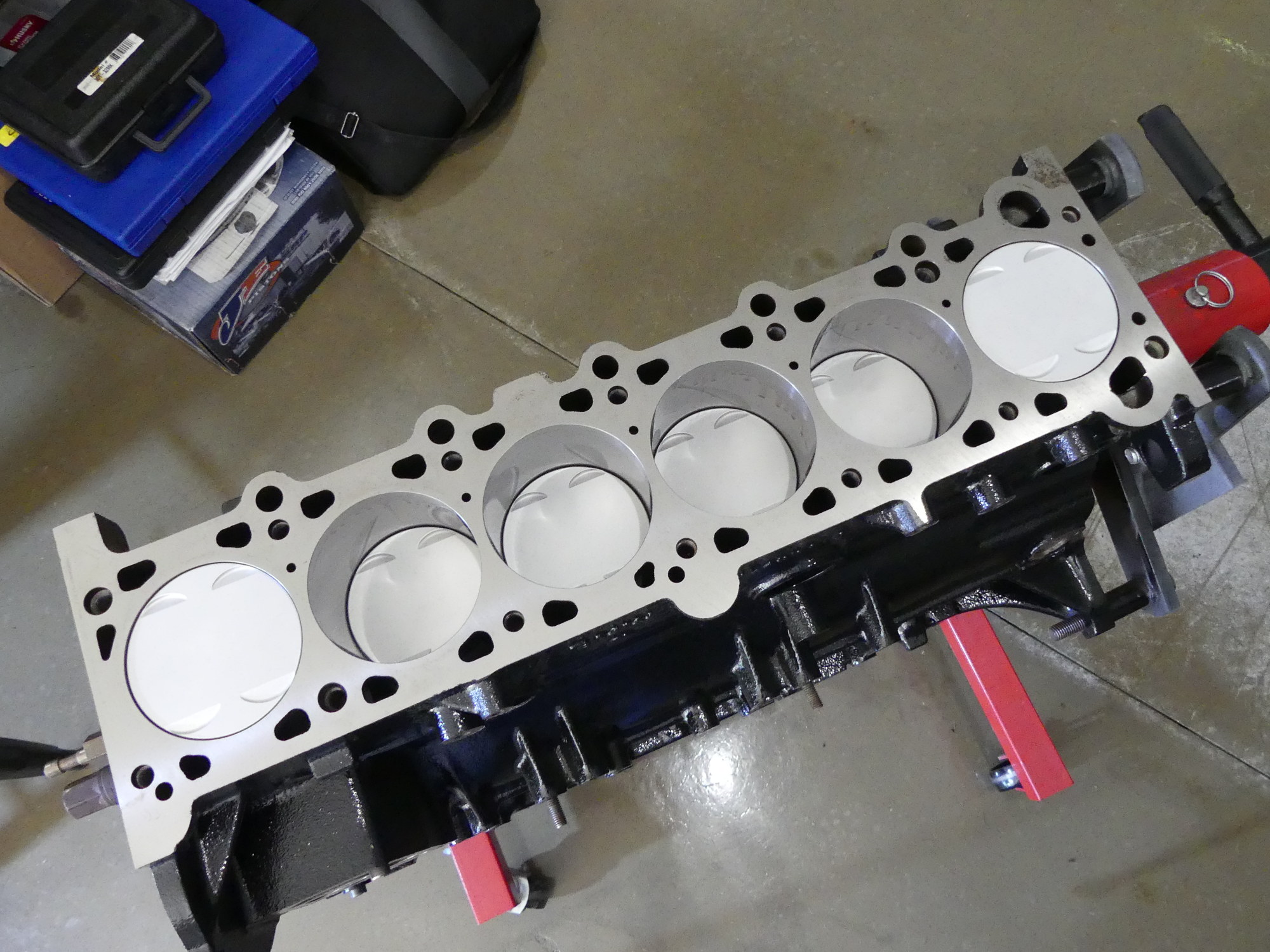 Skip forward a few hours, and this is the result -- all six rods and pistons permanently installed. The ceramic coating on the face of the pistons has reached the point of acceptance that a few manufacturers are using it in production vehicles. |
For the plastigauge test I used the original rod bolts. I applied the recommended torque (5 ft*lbs, 15 ft*lbs plus 70 degrees) and then removed the cap to note the compressed plastigauge strip. Overall the rods were in the 1.5 thousandth region, just like the mains. I don't believe any of the rods had tighter clearances than 1.5 thousandths, but rods 2, 3, and 4 appeared to have some taper to them causing the clearance to vary from an estimated 1.5 to 1.7 thousandths. The worst of the lot was rod #6, which while lacking any taper, produced a plastigauge strip a touch narrower than the others. My estimate is that this rod will be running with 1.7 to 1.8 thousandths clearance. If BMW offered rod bearings in the same granularity as main bearings I would have likely attempted to acquire the next undersize bearing but as that is not an option this will have to do. At some point I'll do an analysis of the plastigauge results to the data I collected earlier.
With the plastigauge test complete I once again used mineral spirits to wipe away the remaining plastigauge material, used compressed air to fully dry the journal and blow away any lint deposited from the towel, and then applied assembly lube to both the journal and each bearing shell. Wrapping things up, I installed the original rod bolts once again and torqued them to 15 ft*lbs so I could securely rotate the crank and check operation.
And this is when I ran into an issue. One of the things I stupidly failed to do in my haste to disassemble the engine was use my digital calipers to measure the depth of the area between the deck of the block and the face of the stock pistons. Had I done that I would have gained an important reference upon which to judge the same distance on my newly assembled rods. I read somewhere on Bimmerforums that this value should be approximately 1.8mm, assuming a stock deck height (i.e. no milling of the block). My machinist milled the deck by 4 thousandths (0.1mm) so I naturally expected the value to be approximately 1.8 - 0.1 = 1.7mm. Surprisingly, I recorded numbers on all the pistons between 1.1 and 1.2mm, or over a half millimeter less than expected -- a red flag if there ever was one.
I immediately called Steve at TEP to inform him of what I found and ask his advice. After I described the issue he said that the 1.8 mm number is not correct and that I should be seeing exactly what I'm measuring -- between 1.1 and 1.2mm for my stock application. I clarified with him that my concern was more with intake valve contact as the exhaust valve reliefs are a lot larger and deeper than stock, but he reiterated that I would not have any issue if the heights were indeed in the 1.1 to 1.2mm range. I have no reason to distrust Steve, particularly given that he has far more experience with these engines and the specific pistons I'm using, but I have to admit this hasn't helped the paranoia I'm experiencing about the successful completion of this project.
Next Up
I had hoped to install the windage tray, oil pump and related stuff today but I had been rolling so much video and taking so many pictures today that my camera filled up the card and then the battery died. So I decided to call it a day and come back tomorrow, at which point I should be able to wrap up the internal bottom end assembly.